Key Takeaways
- Set scope and study intent first so model fidelity, solver choices, and outputs stay consistent with the questions you need answered.
- Use strict conventions for naming, units, signal flow, and subsystem ports so large power system models stay readable and reusable across teams and labs.
- Protect repeatability with shared libraries, small test harnesses, centralized scaling, and stored initialization and solver settings, then keep quality steady with a simple review checklist.
You can keep large electrical models clear, reusable, and testable with a few consistent structure rules.
“Good organization removes the hidden work that slows teams down, like hunting for parameters, guessing signal meaning, or fixing the same wiring mistake in five places.”
It also makes results easier to trust because assumptions stay visible instead of getting buried inside deep subsystems.
Model size is not the main problem; inconsistency is. A well-structured EMT or phasor model can grow for years without becoming fragile, as long as you treat model structure like an engineering interface and not just a drawing exercise.
Set scope and study intent for large power system models
The cleanest model organization starts with a strict scope statement that defines what questions the model must answer and what it will ignore. You should lock down study type, event set, accuracy needs, and the outputs you will use to judge success. That scope then sets the right level of switching detail, control bandwidth, and network size.
Write scope in terms of test cases and measurements, not in terms of blocks you plan to draw. Identify the boundary buses, the measurement points, and the disturbance types you will apply. Keep a short list of non-goals so you do not accidentally mix studies, such as protection timing validation and converter loss estimation, inside the same baseline model.
Standardize naming, units, and signal flow conventions early
Consistent naming and units turn a complex diagram into something you can scan and verify. Signal names should tell you what the value represents, its reference frame, and its units. Port direction should stay consistent across the whole model so you do not need to read every wire to understand causality.
Write these conventions down once and apply them to every new subsystem and library block. A small amount of up-front discipline prevents confusion later when multiple people touch the same models across labs, projects, or course terms.
- Use one bus naming pattern across all voltage levels
- Add unit hints in signal names such as kV, A, pu
- Keep control signals flowing left to right across diagrams
- Reserve one colour scheme for measurement and logging paths
- Document reference directions for power, current, and torque
10 best practices for organizing electrical system models

These practices focus on readability first, then reuse and testability. Each one reduces a specific failure mode such as duplicated logic, hidden scaling, or solver changes that silently alter results. Apply them in order when you refactor an existing model, or as a checklist when you start a new one.
1. Split models by voltage level and functional purpose
Partition the model so each layer has one clear job, such as transmission, medium voltage feeders, or low voltage converter connection. Keep each partition small enough that you can validate it with focused tests. Tie partitions together through defined buses and interfaces, not ad hoc wiring. This keeps changes local when a study scope shifts.
2. Keep top diagrams shallow with clear left to right flow
Use the top level to show structure, not detail. A shallow diagram with a consistent left to right signal flow lets you understand the full system in minutes. Group blocks so the power path is obvious and the control path is separate. Push detail down into subsystems so the top does not become a wiring map.
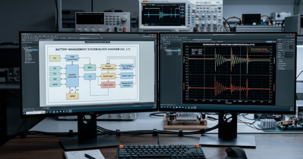
3. Use subsystems to hide detail and expose key ports
Subsystem boundaries should match engineering boundaries, such as a converter, a feeder segment, or a protection relay function. Expose only the ports needed to connect and test that subsystem. Keep internal measurement, scaling, and filter details inside the subsystem so the interface stays stable. Treat subsystem ports like a contract you do not casually break.
4. Separate EMT switching detail from average value sections
Mixing switching models and average value models without clear boundaries makes results hard to interpret. Keep high-frequency switching detail in dedicated areas so time step and solver choices remain obvious. Place average value equivalents in separate subsystems with the same external ports where possible. This supports quick study swaps without rebuilding the diagram.
5. Put reusable components in a shared library structure
Reusable models belong in libraries, not copied across projects. Library blocks keep fixes and improvements consistent, and they reduce the risk of silent divergence between similar subsystems. Keep libraries organized by function, such as machines, converters, networks, and protection. Add short descriptions so new users choose the right block on the first try.
6. Centralize base values, per unit scaling, and unit checks
Scaling mistakes often look like control instability or network faults, so treat unit management as a first-class design task. Store base values and per-unit conversion in one place and reference them everywhere. Add simple unit checks on key signals so errors show up early. Keep conversions close to interfaces, not scattered across the diagram.
7. Use consistent parameter sets with defaults and limits
Parameter sprawl makes models fragile because small edits change behaviour in unexpected ways. Group related parameters into structured sets and keep defaults close to typical studies. Add limits and sanity checks to catch impossible values before simulation starts. Maintain a clear separation between physical parameters and tuning parameters.
8. Separate power network, controls, protection, and measurements
Separate domains so you can review and test each one without distraction. Keep the power network focused on impedances, sources, and switching, while controls and protection stay in their own areas. Route measurements through a dedicated logging layer so instrumentation does not clutter functional logic. This structure also makes it easier to compare control versions against the same network baseline.
9. Add small test harness models for each major subsystem
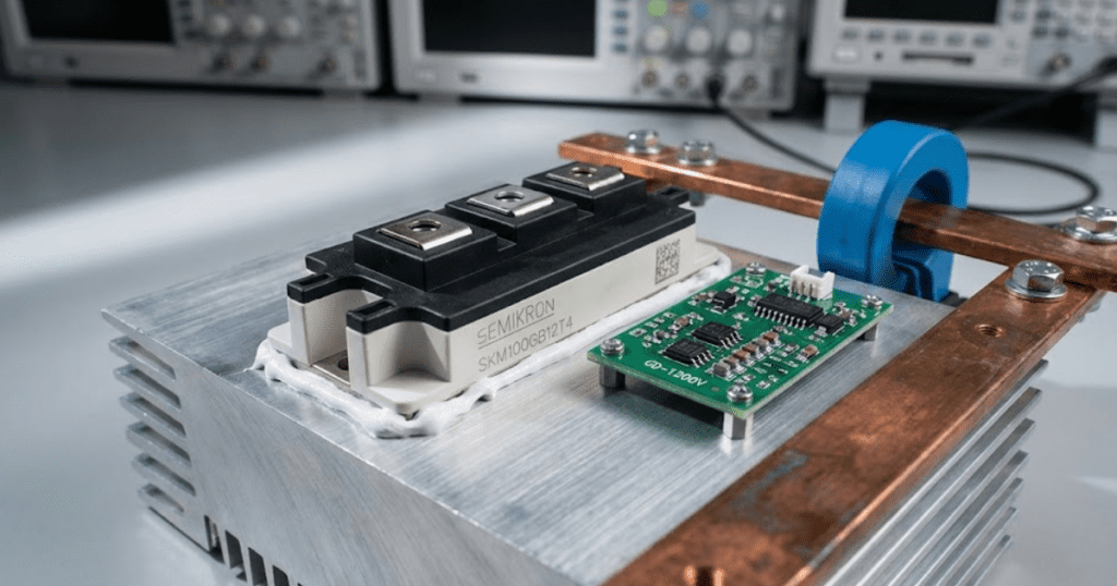
A test harness gives you a fast way to validate a subsystem without loading the full system model. The harness should provide boundary conditions, reference inputs, and checks for expected outputs. A simple harness might feed a converter model with a DC source, a grid Thevenin equivalent, and a step in current reference while logging DC link ripple and line current distortion. Keep harnesses versioned beside the subsystem so updates stay linked.
10. Store solver settings, initialization, and annotations with models
Solver changes can shift results even when the diagram looks identical, so settings must be treated as part of the model. Keep initialization steps close to the subsystem they apply to, and write annotations that state assumptions and limitations. Use consistent initial conditions so test cases are repeatable. Capture any required configuration so someone else can run the model without guessing.
“Subsystem boundaries should match engineering boundaries, such as a converter, a feeder segment, or a protection relay function.”
| Practice | Main takeaway |
| 1. Split models by voltage level and functional purpose | Clear partitions keep changes local and verification focused. |
| 2. Keep top diagrams shallow with clear left to right flow | Top levels should explain structure quickly, not show wiring detail. |
| 3. Use subsystems to hide detail and expose key ports | Stable interfaces reduce rework when internals change. |
| 4. Separate EMT switching detail from average value sections | Clear modelling boundaries prevent hidden solver and fidelity conflicts. |
| 5. Put reusable components in a shared library structure | Libraries prevent copied blocks from silently diverging across projects. |
| 6. Centralize base values, per unit scaling, and unit checks | Central scaling avoids unit errors that look like system instability. |
| 7. Use consistent parameter sets with defaults and limits | Structured parameters keep behaviour predictable and reviews faster. |
| 8. Separate power network, controls, protection, and measurements | Domain separation makes testing and troubleshooting more direct. |
| 9. Add small test harness models for each major subsystem | Harnesses keep subsystem validation quick and repeatable. |
| 10. Store solver settings, initialization, and annotations with models | Repeatable runs require solver and initialization to travel with the model. |
Design subsystem interfaces for reusable simulation models and labs
Reusable simulation models depend on interface discipline more than clever internal implementation. Define what each subsystem accepts and produces, then keep that interface stable across versions. Use clear port names, documented signal units, and explicit reference directions so connections stay correct even when the model is reused in another system.
Interface discipline also supports teaching and team work because students and new engineers can connect blocks without guessing intent. SPS SOFTWARE users often get the best results when subsystems behave like well-defined components, with parameter sets that travel cleanly between lab exercises and research studies. Keep optional features behind parameters, not separate ad hoc copies of the same block.
Use review checklists and model metrics to guide refactors
Refactoring works best when you review structure the same way you review protection settings or control gains. Use a short checklist that flags duplicated logic, hidden scaling, inconsistent naming, and unclear subsystem boundaries. Track a few simple metrics, such as number of duplicate blocks removed, number of interface ports simplified, and count of unit conversions pushed to boundaries.
Good model organization is visible in daily work because debugging becomes faster and test cases become easier to repeat. SPS SOFTWARE fits well when you want transparent, physics-based modelling where the structure stays readable as complexity grows. Treat organization as part of engineering quality, and the model will stay useful long after the first study is finished.