Key Takeaways
- Detailed converter modelling helps you predict control behaviour with confidence instead of relying on simplified assumptions that hide important dynamics.
- Switching effects shape plant behaviour, so capturing ripple, timing, and device nuances is essential for accurate controller tuning.
- High fidelity simulation improves alignment between software and hardware, reducing late stage redesign work.
- Transparent models support stronger engineering judgement because you understand exactly how the converter behaves across conditions.
- A modelling approach that includes switching behaviour helps you deliver more reliable and stable control performance.
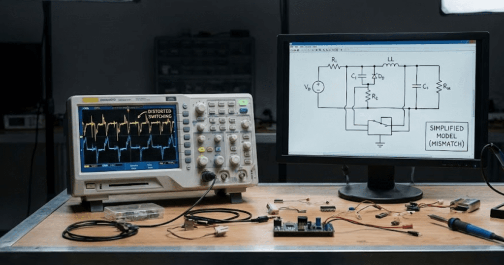
Converter control systems frequently underperform because their underlying models gloss over critical details. When a controller behaves well in simulation but oscillates on the hardware bench, it’s often due to an oversimplified converter model. Engineers sometimes rely on averaged or idealized representations that omit high-frequency switching nuances. Without capturing the real ripple and transient behavior of switches and diodes, subtle instabilities can be missed entirely. As a result, a loop that looked stable in simulation can suddenly go unstable in real life, forcing last-minute re-tuning and costly delays.
High-fidelity modeling is the antidote. Detailed converter models can match physical hardware extremely closely – one real-time simulation study found a model deviating only about 2% from actual device behavior. With transparent, physics-based simulation, engineers see the same oscillations and delays that will appear on the bench. That level of accuracy means controllers are tuned against true-to-life waveforms early in development, helping teams catch problems long before they spin into serious design setbacks. Designing this way builds confidence that the controller will perform as expected on real hardware.
Simplified converter models often mislead controller design
Typical oversimplifications and their consequences include:
- Using averaged models: Treating PWM switches as continuous averages overlooks ripple and fast dynamics. An averaged model can make a converter look stable when in fact it is begging for oscillations.
- Assuming ideal devices: Treating transistors and diodes as perfect on/off switches with no delays removes real-world parasitics. This can hide dead-time effects and reverse-recovery spikes that upset closed-loop control.
- Neglecting parasitic elements: Leaving out stray inductances, capacitances, or resistances in the converter circuitry hides resonances and waveform distortion. In practice, this leads to unexpected overshoot or instability once the real hardware is built.
- Over-simplifying filters: Using a simple RLC filter model without its actual non-ideal behavior ignores how filter components interact at high frequencies. Undetected resonances or phase shifts in the real filter can undermine the designed control loop.
- Decoupling control and power: Simulating the controller separately from the actual switch-level converter can miss key interactions. A digital controller modeled in isolation may behave unpredictably once connected to the full switching network.
Such shortcuts frequently backfire in real converter designs. Engineers then face endless debugging to find why their controller doesn’t match the model. The next sections explain why including switching dynamics in the model is crucial for robust converter control.
“Converter control systems frequently underperform because their underlying models gloss over critical details.”
Switching dynamics are crucial for accurate converter control
Switching ripple and high-frequency harmonics
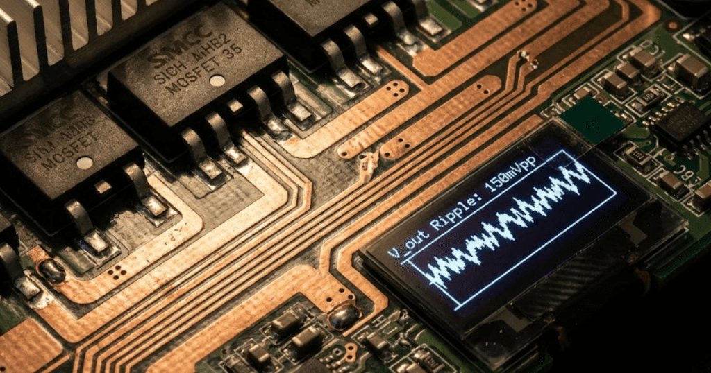
Switching converters introduce high-frequency ripple and harmonics into voltages and currents that affect controller inputs. A controller tuned to a smooth, averaged waveform may misinterpret these ripples as disturbances. In reality, these harmonics can excite filter or control resonances, causing unexpected oscillations or degraded performance. Accurately simulating these high-frequency components lets engineers design filters and compensators to keep the control loop stable under real switching conditions.
Gate delays and dead time
Every semiconductor switch needs finite time to turn on and off, which is often overlooked in simple models. If a simulation ignores dead time, it will not show the brief period when neither transistor conducts. In practice, dead time creates a momentary open circuit in the converter path, introducing current or voltage offsets. Controllers must compensate for this offset; otherwise the loop may develop steady-state error or even subharmonic instability. Capturing these timing nuances in a model ensures the controller accounts for real hardware delays.
Nonlinear device behaviour
Real power devices do not behave ideally. For example, a transistor’s on-resistance and a diode’s conduction drop change with operating conditions and temperature. A simplistic model might treat these as fixed values, missing how they alter the converter’s gain and phase under load. Detailed simulations include these nonlinearities so the controller can be tuned to handle slight gain variations. This avoids surprises like shifts in bandwidth or phase margin when the hardware heats up or operates near its limits.
EMI and coupling effects
High-frequency switching also generates electromagnetic interference (EMI) that can couple into nearby circuits. A simulation without realistic noise sources will not show how switching spikes affect the controller’s sensors or signals. In hardware, EMI can cause false trigger pulses or erratic feedback readings that confuse the control logic. By modeling the switching edges and including realistic noise or EMI coupling, engineers can see these interactions and add shielding or filters as needed. This prevents mysterious errors that would only appear on the lab bench.
In summary, switching events introduce ripple, delays, nonlinearities and noise that directly shape converter behavior. Controllers designed without these dynamics in mind can lose stability or accuracy under realistic conditions. The next section shows how detailed simulation reveals interactions among these effects and control strategies.
Detailed simulations reveal hidden interactions for robust control
Beyond the obvious switching effects, detailed simulation can uncover subtle interactions that simpler models miss. Even small coupling paths or rarely-excited modes can destabilize a converter if ignored. The following list illustrates hidden phenomena that only a high-fidelity model will catch:
- Sensor and sampling limits: Real converters measure voltages and currents through sensors and analog-to-digital converters with finite limits. A detailed model can show when a sensor reading saturates or aliases, causing the controller to see incorrect values and react improperly.
- Filter resonance coupling: Power circuits have parasitic resonances that appear under certain loads. These resonances can amplify particular frequencies in the switching waveform. High-fidelity simulation reveals these resonant peaks so engineers can add damping or adjust control gains to avoid oscillations.
- Source impedance interactions: If the converter is connected to a weak grid or source, the switching waveform interacts with that impedance, causing voltage swings or distortions not seen in isolation. Detailed models include the source impedance so control stability can be tested under realistic supply conditions.
- Thermal and power limits: Detailed models can include how power losses and temperature affect component values. As a converter heats up, device characteristics drift. A high-fidelity model lets you see if a controller remains stable and accurate as conditions change, which a simple model won’t show.
- Multi-loop coupling: Complex converters often use multiple feedback loops (for example, an inner current loop and an outer voltage loop). In detailed simulation, interactions between these loops under switching transients become apparent. This allows robust tuning of each loop in the context of the full system.
In each case, these hidden issues could lead to instability or poor performance if only basic behavior was modeled. Detailed simulations bring them to light, allowing engineers to design controllers that truly handle real-world conditions. Teams that invest in model fidelity early gain confidence that their design will translate smoothly from simulation to hardware.
High-fidelity models ensure control reliability from simulation to hardware

Realistic simulation tightly links what happens in software to what engineers see on the hardware bench. By including full switching behavior and component nuances, a high-fidelity model produces waveforms and responses nearly identical to the physical system. In fact, FPGA-based simulators now achieve integration steps under 100 ns – about 100× shorter than typical converter switching periods – capturing every ripple and transient. With this level of detail, the simulated converter behaves just like the real one, so a controller tuned in the model performs reliably on the hardware.
This fidelity pays off in productivity. Teams can skip extra hardware tweak cycles because the design has already been validated in simulation. Accurate models reduce the risk of late surprises in system tests, saving weeks of debugging. Moreover, the insights from precise waveforms help refine filters and compensators for best performance. In short, high-fidelity simulation bridges the gap to hardware and lets engineers deliver stable, accurate converter controls on the first try.
“Detailed simulations bring them to light, allowing engineers to design controllers that truly handle real-world conditions.”
SPS SOFTWARE ensures converter control fidelity
Building on the insights above, SPS SOFTWARE delivers the high-fidelity modeling engineers need. We offer transparent, physics-based converter models that include switching ripple, dead time, and device non-idealities. As a result, engineers and students using SPS SOFTWARE can tune their controllers against exactly the waveforms they will see in reality. Our open-model approach means every device equation and parameter is visible and adjustable, so users know exactly how their system behaves. This builds confidence that the controller will perform as expected on real hardware.
Our platform integrates seamlessly with common workflows like MATLAB/Simulink, so detailed converter models flow directly into control design tools. It helps users catch issues early by making simulation results as close to reality as possible, without sacrificing convenience. The outcome is clear: engineering teams save time and money because they design and test controllers on the right model from the start, avoiding costly late-stage revisions.
Advanced users leverage the ARTEMiS toolbox as a plug-in solver within Simscape Power Systems (formerly SimPowerSystems) to achieve real-time accuracy. Practically, this means building the electrical model in Simscape Electrical™ as usual, and then selecting ARTEMiS as the fixed-step solver when running on real-time hardware. ARTEMiS augments the standard model by automatically partitioning the network and applying numerical stabilization techniques so the simulation remains stable at the chosen time step. The result is that engineers can simulate complex power systems – like microgrids or multi-motor drives – in real time without adding artificial delays or simplifying the model. In essence, ARTEMiS serves as a real-time execution engine that ensures the Simscape model’s fidelity is preserved at high speed.
FPGA-based solvers have become essential because modern electrical systems often involve phenomena that unfold faster than what traditional CPU solvers can handle. High-frequency power electronic devices, such as silicon carbide (SiC) or gallium nitride (GaN) converters, switch so quickly that to simulate them accurately, you need extremely small time steps. FPGAs can compute these tiny step simulations in parallel, which is something general CPUs struggle with at scale. By using FPGAs, simulators can capture every rapid transient and switching event, so they accurately model everything from high-speed motor drives to lightning-fast protection circuits. Essentially, FPGA solvers ensure that a simulation’s resolution is fine enough to mirror reality in cases where even microsecond-level steps would blur important details.
CPU-only real-time simulations are limited by the sequential nature and clock speed of general-purpose processors. As simulation models grow in complexity – with more nodes, switching elements, and control loops – a CPU has to perform more calculations in the same fixed time step. Eventually it hits a point where it cannot finish all computations before the next step is due, leading to missed deadlines or the need to increase the step size. Engineers often must simplify models under CPU-only constraints, for instance by grouping components or reducing switching speeds, which can omit critical dynamic behaviors. Moreover, some power electronics simulations involve very stiff equations that are prone to numerical instability on a CPU unless the step size is made larger. All these factors mean a CPU-only approach might not faithfully simulate extremely fast or large-scale systems, limiting the scenarios you can confidently test.
Yes, one of the big advantages of advanced real-time simulators is their ability to explore and predict rare failure conditions that might be hard to recreate otherwise. Because these simulators can run highly detailed models, engineers can insert fault conditions or extreme events into the simulation and observe the outcomes. For instance, a real-time simulator can model what happens if a circuit breaker in a power grid fails to open on time, or how a multi-inverter renewable energy system behaves during an unplanned islanding event. By accelerating or repeating scenarios in the simulator, you might discover failure modes that would normally take years of actual operation to surface. Importantly, when the simulation runs in real time, it can interact with actual protective devices or controllers, revealing how the entire system (both hardware and software) responds to those rare events. This predictive capability helps engineers design more robust systems and put safeguards in place for events that are unlikely but possible. In short, high-fidelity real-time simulation enables a proactive approach to reliability, where potential failures are understood and mitigated in advance.