Key Takeaways
- Rigorous preparation gives integration teams confidence that models will behave consistently once connected to hardware, reducing costly surprises and delays.
- Accurate physics based components provide the foundation for hardware tests that reflect how systems respond under stress.
- Real time optimization steps help models meet fixed execution deadlines so you can run hardware tests without overruns or instability.
- Early interface planning minimizes rework by ensuring every signal, channel, unit, and scaling is aligned before the system reaches the bench.
- Thorough review practices give teams a structured path to validate behaviour, timing, and assumptions before beginning hardware trials.
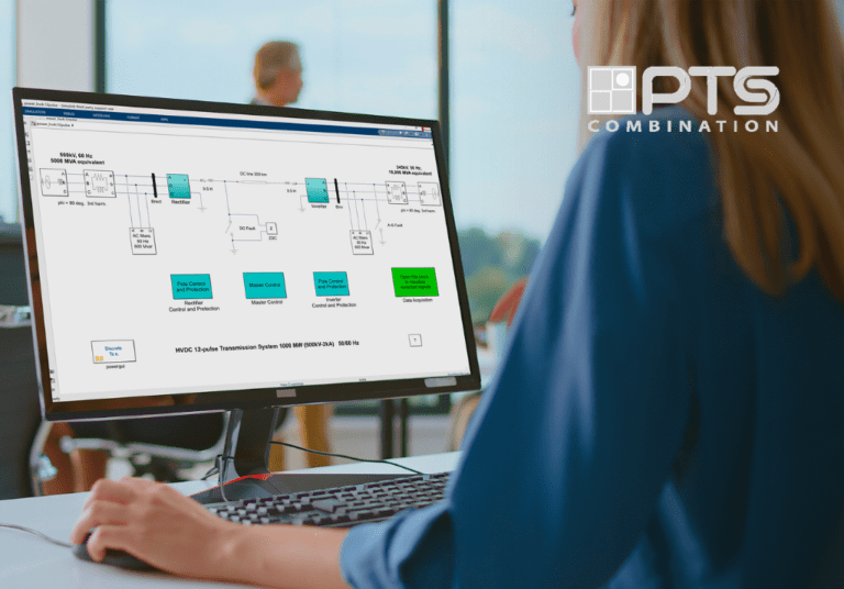
A single incorrect simulation model can derail an entire hardware test plan. Integration teams often find that models running perfectly on a desktop behave unpredictably under real-time constraints. We have seen projects get stuck when a controller model suddenly can’t meet timing on target hardware or when signal interfaces don’t match the physical bench. Without robust preparation, hardware-in-the-loop (HIL) tests yield unreliable results or even critical failures. For example, modern real-time labs can simulate complex power grids with around 10,000 nodes, meaning even a small modeling error can cascade across the system. Rigorous model preparation addresses these issues: verifying fidelity, optimizing performance, and double-checking interfaces up front. The payoff is safer testing, faster iteration, and a higher level of trust in the results.
Accurate models prevent hardware testing surprises
Precise physics-based modeling is the foundation of reliable hardware testing. If a model uses oversimplified components or fixed signals, its behavior may deviate from the actual system under test. Engineers should ensure each component is grounded in the real system’s physics and parameters. For instance, neglecting losses in a power converter or idealizing sensor responses can cause mismatches that only appear when the model is connected to real hardware. This kind of discrepancy forces teams to chase down issues outside the simulation, consuming valuable project time.
For example, real-time labs like Oak Ridge’s grid simulator can handle around 10,000 nodes, and one open-source platform even simulated 24,000 electrons in real time. Such scale highlights that in large simulations even minor errors can multiply. Teams should calibrate models against measurements and validate behavior under all expected conditions so the simulation reliably mirrors reality. When each component is accurate and transparent, engineers can adjust parameters on the fly and trust that changes produce meaningful outcomes.
“Teams should calibrate models against measurements and validate behavior under all expected conditions so the simulation reliably mirrors reality.”
Real-time performance requires an optimized model

Even an accurate model will fail if it can’t run fast enough in real time. Engineers must streamline models so that every computation meets the hardware clock. Common strategies include using fixed-step solvers and synchronous subsystems, merging or flattening hierarchical blocks, and removing or simplifying computationally heavy elements. For example, a multi-domain converter model might run electrical physics at 10 μs steps and thermal effects at 100 μs steps, forcing careful timing choices.
- Solver and step size: Fix the solver type and time step to match the real-time hardware rate, ensuring deterministic execution and avoiding variable-step uncertainty.
- Simplify models: Remove logging scopes, diagnostic blocks, and any algebraic loops or rare functions that slow execution.
- Flatten and optimize subsystems: Merge cascaded blocks and use efficient code-generation options to reduce computational overhead.
- Data types and fixed-point: Select data types (for example, fixed-point) that suit the real-time target and minimize expensive type conversions.
- Code generation and deployment: Generate optimized C/HDL code for the real-time platform, compile it, and fix any code-generation issues before the test.
- Lean signal paths: Include only necessary signals and calculations in the execution loop to reduce load and preserve timing.
These steps turn a design model into one that meets real-time constraints. The result is fewer deadline misses and repeatable execution timing. Overall, optimized models ensure the hardware can compute every step in time, avoiding numerical instabilities and overruns.
Early interface planning prevents integration setbacks
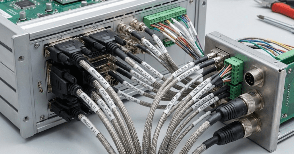
Hardware tests often fail because of mismatched signals or overlooked I/O requirements. Early in the project, teams should plan out every interface between the model and the test equipment. This means defining each input and output channel, its units, range, and expected data type before building the HIL setup. Setting up this interface specification early prevents surprises like a voltage signal plugged into the wrong amplifier or a timing mismatch on a communication bus. It helps to create documentation of all channels and signal mappings from the start.
Teams also double-check unit and scaling consistency. They confirm that every model signal uses the same units the hardware expects and that digital formats (like ADC bit ranges or communication protocols) line up. For instance, mapping Simulink block outputs to hardware channels and verifying them with simple test signals can catch alignment issues early. Documenting channel assignments, expected value ranges, and connector mappings becomes a concrete checklist for the integration phase. In practice, treating interface setup as a parallel task to modeling cuts days of debugging. By integration time, teams can plug in the model with confidence, focusing on functionality rather than chasing mismatches.
Thorough model reviews are the final check before hardware tests

“A single incorrect simulation model can derail an entire hardware test plan.”
Verify component behavior
Engineers double-check each component by testing it in isolation if possible. For example, one might drive a simulated sensor with a known input waveform and ensure the output matches theoretical or experimental data. Checking corner cases and sensor noise responses catches modeling issues early. Custom code and lookup tables are examined here as well, making sure every block works as intended and its outputs align with expectations. This component-level testing means any error is caught in context and doesn’t derail larger tests.
Test edge-case scenarios
A thorough review also covers abnormal conditions. Engineers simulate fault scenarios, extreme inputs, and boundary conditions to see if the model response stays realistic. For instance, they might simulate a sudden loss of power or a sensor zero reading to validate protective logic and controller robustness. Spotting unrealistic or unstable behavior in these simulations prevents surprises during actual testing. These stress tests serve as a sanity check, ensuring that any hidden assumptions in the model do not break under extreme conditions.
Check performance and timing
During review, teams confirm that model execution is within acceptable bounds on the target hardware. This includes verifying that the model meets its intended sample time without overruns. A simple compile-and-run test on the real-time platform reveals if any task is taking too long. Engineers watch for missed deadlines or solver warnings, and ensure any hardware I/O (like PWM or ADC blocks) use the correct timing. Catching such bottlenecks now avoids integration problems later on the real bench.
Document assumptions and interfaces
Finally, a model review includes documentation. Engineers recap all important assumptions, parameter values, and interface mappings. A summary list of state variables, initial conditions, and solver settings confirms that nothing was overlooked. By reviewing a documented summary of model settings, teams ensure every detail aligns with the hardware test plan. Well-commented models and clear notes also help with handover, so anyone running the test knows exactly how everything is set up.
Each of these review steps is a chance to catch discrepancies before a single wire is hooked up. The result is a model that has been vetted from every angle, giving engineers confidence to proceed to hardware-in-the-loop experiments.
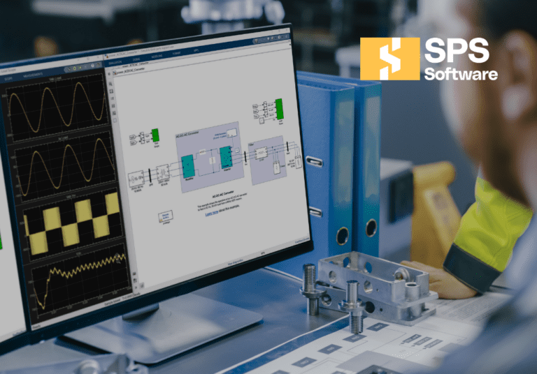
SPS SOFTWARE integrated model preparation workflow
As a final step, integration teams bridge design and test with one consistent model to eliminate translation errors. This integrated approach means outputs correlate across contexts, and engineers can focus on interpreting results rather than reconciling tools. SPS SOFTWARE offers this kind of platform: it uses open, transparent component libraries and direct MATLAB/Simulink integration so the model you validate in simulation becomes the code running on the real-time system. This eliminates redundant work and helps your team focus on results instead of tool configuration. The outcome is faster iterations and more trust in the final results.