Free Trial
Free Trial
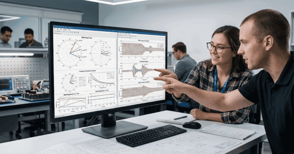
Engineers discussing SimPowerSystems simulation workflows in an office meeting.
Power Systems, Simulation

Why Electrical & Power System Simulation is Critical in Engineering

Engineers can no longer design today’s complex power systems safely without advanced simulation. Modern electrical grids are complicated, integrating renewable energy and distributed generation. This soaring complexity introduces countless potential failure modes as cumulative distributed energy resource (DER) capacity in the U.S. will reach 387 GW by 2025, multiplying the elements engineers must manage. Development cycles are tighter than ever and reliability standards unforgiving, making it impractical and risky to test new designs directly on live power infrastructure. Real-time simulation offers a powerful alternative: it provides a safe, high-fidelity virtual environment to validate and refine power system designs, catching issues early, accelerating development, and ensuring systems will perform reliably – all without costly physical prototypes or dangerous in-field experiments. Simulation bridges the gap between concept and operation, enabling engineers to innovate swiftly despite rising complexity.

Complex power systems require simulation for safe testing

Electrical power systems have grown far too intricate to rely on trial-and-error field testing. A single grid involves thousands of components, any of which can behave unexpectedly. Physically testing extreme scenarios on the real grid or a prototype is not only expensive but potentially catastrophic. A misstep can cascade into equipment damage or widespread outages, and we know major power interruptions carry enormous economic costs. U.S. businesses lose around $150 billion annually due to outages. Simulation, by contrast, lets engineers safely recreate these scenarios in a controlled digital setting.

Using detailed power system models, an engineer can impose severe faults, rapid load fluctuations, or unusual configurations virtually, all without endangering real equipment or customers. High-fidelity simulators replicate electrical behavior down to microsecond transients, so even fast-acting phenomena like inverter trips or protection-system responses can be observed closely. This means you can explore worst-case events (a cascading line failure, a sudden surge of solar generation, etc.) and see how the system holds up long before any physical implementation. Such safe virtual testing reveals vulnerabilities early and prevents costly surprises later. As power systems become more complex and less forgiving, simulation has become the only practical way to test new designs and control strategies without putting people or infrastructure at risk.

Real-time simulation offers a powerful alternative: it provides a safe, high-fidelity virtual environment to validate and refine power system designs, catching issues early, accelerating development, and ensuring systems will perform reliably.

Simulation accelerates design and reduces failure risk

Engineering teams are under pressure to deliver better power system solutions on tighter schedules. Traditional build-and-test cycles – constructing prototypes, waiting for field tests, iterating after failures – are simply too slow and risky today. Simulation fundamentally changes this equation by allowing much faster, iterative development. You can model a new grid control algorithm or substation design and start testing it virtually within hours, not months, quickly refining the design without waiting for hardware. This accelerated design loop gets innovations to market faster and slashes development costs. Notably, one power plant project that leveraged high-fidelity simulator training saw a 15% reductionin commissioning time, illustrating how virtual testing streamlines deployment.

Simulation also helps you find and fix problems when they’re easiest (and cheapest) to solve. Catching a design flaw early can save tremendous hassle – an error found in operation can cost hundreds of times more to fix than one caught at the design stage. Real-time simulation makes this early discovery possible: engineers can subject control software or equipment models to thousands of scenarios (faults, load spikes, component failures) in the virtual world and identify weaknesses well before anything goes live. By the time you move to physical prototyping, you’re dealing with a far more mature and proven design. 

This dramatically reduces failure risk during development and after deployment. Instead of learning from costly mistakes in the field, your team learns safely from simulations. The result is a faster design cycle with fewer iterations wasted on rework, and far greater confidence that once the system is built for real, it will work as intended from day one.

  • Early virtual prototyping: Simulation lets you test conceptual designs and control strategies immediately, so you can iterate without waiting for physical prototypes.
  • Rapid scenario testing: Automated simulations can run hundreds of scenarios (grid disturbances or equipment outages) overnight. Engineers get instant feedback and can refine designs in days instead of months.
  • Safe failure exploration: You can push systems to the brink in simulation – creating rare faults or extreme overloads – without real-world consequences. This uncovers edge-case failures that traditional testing might miss while keeping hardware safe.
  • Fewer physical prototypes: By validating ideas in software first, teams often build far fewer hardware prototypes. Expensive testing is reserved only for final, well-vetted designs, cutting costs and development time.
  • Collaborative design: Simulation provides a shared sandbox where electrical engineers, control developers, and protection experts can experiment together. Issues at component interfaces are caught early, before they become costly integration problems.

With these advantages, real-time simulation has become a catalyst for both speed and quality in power engineering. It empowers your team to move fast but safely. Engineers can try bold ideas in a risk-free digital environment, refine them quickly, and avoid the nightmare of late-stage failures. Simply put, simulation-based workflows produce better designs in a fraction of the time of traditional methods.

High-fidelity simulation bolsters reliability and performance

Once a power system moves from design into operation, there’s zero room for error thus reliability and efficiency must be assured. High-fidelity simulation plays a critical role in meeting these goals. Because real-time simulators can model electrical behavior with extreme precision, engineers can fine-tune systems for maximum stability, efficiency, and robustness. Advanced electromagnetic transient (EMT) simulations let utilities study how inverter-based resources respond to grid faults in far greater detail than traditional models. The North American Electric Reliability Corporation (NERC) has even warned that these detailed simulations are necessary to identify and mitigate emerging reliability risks on modern grids. Engineers use high-fidelity models to verify that protective devices and controls react correctly to disturbances. Every subtle dynamic can be validated, giving operators confidence that the real system will perform as expected.

Ensuring system reliability

Real-time simulation allows engineers to apply countless “what-if” disturbances and verify the grid remains stable. They can simulate generator trips, short-circuits, or other faults and see how the system reacts, exposing and fixing weak links long before any real event. By the time a design is deployed, it has been proven through thousands of virtual trials which dramatically reduces the chance of unexpected outages.

Real-time simulation is now an engineering essential

The trajectory of power engineering has made real-time simulation indispensable. Faced with soaring grid complexity and uncompromising reliability demands, engineers worldwide have integrated simulation into every stage of development. In fact, leading researchers caution that without state-of-the-art simulation tools, utilities may struggle to maintain reliability as the grid undergoes change. High-fidelity, real-time models are no longer a luxury as they are central to how we design resilient systems today. Utilities and manufacturers now use real-time digital twins to validate designs before construction, knowing that every critical component should be vetted virtually. This approach has proven so effective it’s becoming standard across other high-stakes industries. Real-time simulation is the new benchmark for de-risking complex engineering projects.

High-fidelity simulators replicate electrical behaviour down to microsecond transients, so even fast-acting phenomena like inverter trips or protection-system responses can be observed closely.

The rise of real-time simulation doesn’t replace human ingenuity, so when every hypothetical scenario can be explored on a simulator, design teams gain a deeper understanding of system behavior and better decisions. And when projects go live, stakeholders have peace of mind knowing the system has already been through the digital wringer. Real-time simulation has become an engineering essential by bridging the gap between theory and practice. It allows us to tackle power system challenges swiftly and safely, delivering resilient, high-performance designs on tight timelines.

OPAL-RT empowering engineers with real-time simulation

Building on the understanding that real-time simulation is essential in modern power engineering, OPAL-RT has long focused on equipping engineers to meet these complex challenges. The company provides real-time simulation platforms that allow teams to model and test everything from individual power electronics devices to entire power grids with uncompromising fidelity. By using its Hardware-in-the-Loop and digital twin solutions, engineers can safely validate control strategies and equipment designs against all the scenarios – multi-source grids, fast transients, fault conditions – long before construction. This means you catch design issues early, refine system performance, and confidently achieve reliability targets without slowing development.

This approach aligns with the pain points and benefits outlined above. Its real-time simulators and software tools empower organizations to handle soaring system complexity on tight schedules while maintaining the highest standards of safety and reliability. Across the energy sector and beyond, the company is a trusted partner for innovators seeking to bridge the gap between concept and operation. From utilities adding renewables to R&D teams developing new converters, engineers can lean on this real-time simulation expertise to accelerate their progress. The result is not just faster design cycles, but more resilient power systems ready to meet real demands – which is why power system simulation has become critical in engineering

Electrical simulation lets you test extreme conditions without risking equipment or infrastructure. Instead of exposing assets to destructive scenarios, you can study performance in a controlled digital environment. This gives you confidence that your system can withstand faults and stresses. OPAL-RT provides simulation tools that help you reach this level of safe validation with accuracy and speed.

Simulation software helps you shorten design cycles while lowering costs by catching design flaws early. You can model grid behaviour, validate controls, and fine-tune settings before moving to hardware. This avoids wasted time and rework, ensuring smoother implementation. OPAL-RT supports these workflows with high-performance simulators designed to help you deliver reliable outcomes faster.

High-fidelity models capture system behaviour down to microsecond details, allowing engineers to validate protective responses and stability. Without this precision, hidden risks could pass unnoticed until operation. Using accurate simulations gives you confidence that your systems will perform as expected. OPAL-RT specializes in real-time platforms that bring this level of fidelity to your projects.

Renewables add variability and complexity to power grids that traditional testing cannot fully cover. Real-time simulation lets you model inverter dynamics, rapid output shifts, and grid interactions in detail. This ensures you can design controls that keep systems stable under changing input. OPAL-RT helps renewable project teams use real-time testing to accelerate integration and maintain reliability.

OPAL-RT provides real-time simulation platforms that engineers use to validate concepts and reduce development risk. These tools let you refine designs virtually and be confident before building prototypes. The result is faster project timelines and higher assurance of success. Engineers across energy and academic sectors trust OPAL-RT to support their most complex validation needs.

Engineer assembling real-time simulation hardware for SimPowerSystems testing in a technology lab.
Industry Application, Simulation

Differences & Applications Between Electrical Modeling vs  Simulation Software

Great testing starts when your models and simulations tell the same story. Missed physics, hidden latencies, or solver limits can mislead your design choices. Teams that separate description from execution spot risks earlier and cut lab time. That is why understanding modelling tools and simulation engines matters to every power project.

Power engineers, hardware-in-the-loop (HIL) testers, and researchers face the same tension. You need rich models to capture control intent, and you need fast simulation to exercise edge cases. Tool selection shapes requirements flow, lab architecture, and test coverage. The right mix gives you speed, confidence, and room for future changes.

Why engineers compare electrical modeling and simulation tools

Power projects rarely fail because a single component looked wrong; they fail because interactions were misunderstood. Comparing modelling suites and simulation engines helps you decide how to represent those interactions with the fidelity your team can maintain. Modelling focuses on structure, parameters, and control intent so that everyone shares the same electrical story. Simulation focuses on numerical behaviour across time so that you can probe stress, stability, and safety. You compare tools to balance model readability, solver performance, reproducibility, and lab integration.

Budget and schedule also force tradeoffs that are easier to manage with the right pairing. High-fidelity models with slow solvers stall project gates, while fast solvers with incomplete models hide integration risk. Comparing toolchains early keeps measurement, automation, and version control aligned across design, software, and testing. That alignment limits rework, clarifies ownership, and shortens the path from concept to field trials.

What electrical modeling software does for power system design

Electrical modeling software helps you capture design intent as consistent, shareable representations of your system. It lets teams encode schematics, control logic, and ratings as data their simulators can execute. Good models separate parameters from structure, which improves reuse, reviews, and change tracking. Clear models shorten onboarding for new teammates and make subsequent simulation runs meaningful.

Topology capture and parameter management

Modelling tools help you define buses, branches, converters, and sensors without jumping into solver settings. You assign ratings, impedances, delays, and limits as parameters that can be versioned and reviewed. Named parameters feed bill-of-materials estimates, protection studies, and controller targets. Structured topology also makes it easier to maintain variants for different power levels, grid codes, and suppliers.

Parameter sets let you switch between rated, cold-start, and faulted conditions without redrawing the circuit. Templates reduce copy‑paste errors, improve consistency, and speed up peer review. When models track units and ranges, you catch mismatches early, before those numbers reach the lab. That discipline improves traceability from requirements to simulation cases and hardware settings.

Control design scaffolding

Control engineers need a place to express state machines, PWM strategies, and observers alongside the plant. Modelling suites let you partition plant and control while keeping signal names, timing, and interfaces consistent. You can lock interfaces, share test vectors, and keep clear change logs between control and plant teams. This scaffolding shortens handoff to firmware, reduces ambiguity, and increases reuse across projects.

When the model already reflects quantization, saturations, and delays, later simulation behaves more like the bench. Control gains can be tied to parameter sets, which supports sweep studies and autotuning workflows. Clear structure also allows formal reviews, static checks, and lightweight unit tests of control pieces. Those practices reduce integration issues and improve safety margins during field trials.

Physics-based component libraries

Component libraries give you validated blocks for machines, converters, lines, and protective elements. Good libraries document reference equations, assumptions, and applicable operating ranges. When those details are present, reviewers can judge fitness for use and predict limits. Shared libraries also keep multi‑team projects consistent, since everyone pulls from the same sources.

Library quality matters because subtle modelling choices change controller robustness and loss estimates. For example, saturation and hysteresis treatment in machines can affect current ripple and torque prediction. Clear options for ideal, average, and switching models let you trade speed for fidelity as needed. Documentation that cites validation data builds the trust you need for later certification steps.

Interoperability with design toolchains

Modelling is more useful when portable across toolchains, code bases, and labs. Support for Functional Mock-up Interface (FMI) and Functional Mock-up Unit (FMU) formats lets teams exchange models without rewriting code. Clear import and export options cut time spent on glue code between analysis tools, automation scripts, and test equipment. Interoperability also helps with vendor audits, since reviewers can execute models in their preferred tools.

Version control hooks and diff‑aware formats simplify change review and traceability. Structured data makes parameter sweeps reproducible, which benefits certification and internal quality checks. Shared model repositories reduce duplicated effort across teams, sites, and partners. The result is a smaller set of models that serve more use cases, with fewer surprises.

Electrical modeling software should make structure explicit, standardize parameters, and clarify control interfaces. Strong modelling practices set the baseline for every later experiment. Teams that invest here enjoy faster reviews, cleaner handoffs, and fewer late fixes. That foundation makes subsequent simulation runs faster to set up, easier to audit, and more predictive.

Great testing starts when your models and simulations tell the same story.

How electrical simulation software improves testing and validation

Simulation converts your static models into time‑domain behaviour you can interrogate before you touch hardware. Electrical engineering simulation software brings solvers, schedulers, and tooling that mirror conditions you care about. Good simulation helps you surface edge cases, size components, and prepare protection settings. It also makes lab sessions more productive, since you arrive with known risks, extracts, and scripts.

Scenario exploration and edge cases

Simulation lets you vary topology, loads, and operating points without touching the lab bench. You can sweep temperature, aging factors, and sensor errors to see how margins shift. Event scheduling allows precise sequencing of faults, reclosers, and controller failovers. Those sequences reveal interactions that are hard to stage physically, such as rare overlaps of delays and thresholds.

Monte Carlo runs expose combinations that manual testing misses, while keeping seed control for reproducibility. Parameter sweeps generate response surfaces that guide sizing choices for inductors, capacitors, and heat sinks. Time compression lets you preview slow processes like thermal drift and state of charge. Records from these runs become living documentation for safety reviews, field support, and future upgrades.

Closed-loop tests with HIL

Hardware-in-the-loop (HIL) connects the simulator to your controller so that code sees realistic signals. Low latency digital input and output, plus accurate timing, makes switching behaviour and protection logic meaningful. Plant models can run at fixed steps or real time, depending on scheduling and available compute. You can stage faults, dropped packets, and sensor failures while keeping hardware safe.

Software-in-the-loop (SIL) and model-in-the-loop (MIL) complete the chain before HIL, which reduces risk at each stage. Field programmable gate array (FPGA) support brings microsecond timing that suits power electronics, motor control, and grid studies. Power hardware-in-the-loop (PHIL) adds actual power flow for converter testing, with careful management of stability and ratings. Closed‑loop practice yields better tuned controllers, safer startups, and shorter trips to the field.

Faster iteration with compiled solvers

Compiled solvers accelerate long runs so you can evaluate more scenarios within a fixed test window. Switching models that support average mode let you trade waveform detail for cycle‑accurate dynamics. Adaptive step logic focuses effort where transitions occur, which saves compute while preserving key effects. Batch execution with parallel workers turns nightly runs into next‑day plots and metrics.

Careful solver selection also avoids the numerical artefacts that sometimes appear with stiff systems. You can keep frequencies of interest in band, and still finish runs within practical time limits. Clear reporting on solver settings makes those results defensible during peer review. This pace of iteration improves confidence when projects hit gate reviews, audits, and design freezes.

Regression and compliance validation

Simulation suites track scenarios as test cases, complete with pass and fail criteria. You can script waveform checks, limit violations, and settling times so that results are repeatable. Those checks align with standard ranges and customer targets, which saves time later. Versioned scenarios also help during supplier changes, since you can re‑run the same tests and compare metrics.

When the lab turns up a corner case, the scenario can be reproduced in simulation and then widened. That loop shortens mean time to fix, improves traceability, and teaches the team which margins matter most. Compliance bodies appreciate documented evidence that links requirements to traces, tables, and scripts. Regression suites prevent silent drift, especially when multiple teams contribute to the same code base.

Simulation pays off when it shrinks uncertainty before you book lab time. Electrical engineering simulation software should expose edge cases, support closed‑loop testing, and scale across solvers. A thoughtful setup gives you repeatable results that hold up in design reviews and safety audits. That discipline turns models into evidence you can trust in production decisions.

Key differences between electrical modeling and simulation software

The main difference between electrical modeling software and simulation software is that modelling defines the system’s structure and parameters, while simulation executes those definitions over time to predict behaviour.

Modelling captures topology, control intent, and constraints as a portable description. Simulation brings numerical methods, scheduling, and data capture that turn that description into waveforms and metrics. Treating them as distinct reduces confusion when teams discuss accuracy, performance, and ownership.

Most projects use both, often within the same suite, but the roles still differ. Clarity about the handoff keeps parameters in one source of truth, and keeps solver settings tied to test plans. The table below summarizes contrasts that frequently matter during tool selection and process reviews. Use it to align expectations across modelling leads, test engineers, and reviewers.

AspectModelling softwareSimulation softwareValue to teams
Primary purposeDescribe structure, parameters, and control intentExecute models over time to produce waveforms and metricsKeeps responsibilities clear and reduces disputes over results
Typical usersSystem architects, control engineers, reviewersTest engineers, analysts, automation staffImproves collaboration and handoffs
OutputsSchematics, parameter sets, interface definitionsTime traces, logs, statistics, limitsLinks design to measurable outcomes
Time baseStatic or configuration‑orientedDiscrete time, continuous time, or mixedMatches solver to the physics of interest
Performance focusMaintainability, reuse, claritySpeed, numerical stability, throughputBalances readability with compute efficiency
Integration pointsRequirements, version control, documentationHIL rigs, data stores, reporting toolsSupports both governance and testing
Risks from misuseOut‑of‑date parameters, unclear interfacesMisleading results from wrong solver settingsGuides reviews to catch the right issues

Applications of electrical power system analysis software in engineering projects

Electrical power system analysis software ties models and simulation to actionable engineering studies. Engineers use it to calculate flows, stress, and stability across operating points and events. Clear studies guide settings, hardware selection, and safety reviews for projects of many sizes. These applications show how analysis tools cut risk, shorten lab time, and inform commissioning.

Microgrid planning and protection studies

Projects that mix generation, storage, and loads need steady‑state and transient checks. Power flow, short circuit, and protection coordination studies come from the same data model when set up well. Voltage regulation and islanding require attention to limits, droop settings, and reserves. Analysis tools help teams define operating modes, ride‑through settings, and safe reconnection paths.

Disturbance cases reveal how converters share current during faults, and how relays see events. Renewable variability affects state of charge and feeder voltage, so studies include profiles and contingencies. Detailed models of inverters, filters, and lines make protection settings both selective and robust. The outputs inform controller tuning, feeder hardware choices, and operator playbooks.

Vehicle powertrain and energy storage

Traction systems involve converters, machines, and batteries with tight timing and thermal limits. Analysis runs sweep drive cycles to estimate losses, temperatures, and lifetime effects. Fault cases test isolation, contactor sequences, and limp‑home strategies that protect occupants and assets. Battery models track ageing, state of charge, and impedance, which shapes performance and warranty.

Motor control strategies are assessed for stability, noise, and efficiency across speed and load. Hardware sizing depends on cooling assumptions, packaging, and expected duty cycles. Control and plant teams share a single model, so firmware changes reflect into energy and thermal projections. That link keeps program risks visible and supports sign‑off across engineering, quality, and safety.

Aerospace power distribution and redundancy

Aircraft power systems prioritize weight, fault tolerance, and clear isolation during abnormal events. Analysis software evaluates bus transfer logic, load shedding, and generator limits under multiple failures. Transient cases examine arc risks, contactor timing, and converter overshoot. Studies also assess electromagnetic compatibility ranges that affect sensors and communication.

Redundancy planning includes alternate feeds, hot spares, and preferred fault clearing paths. Thermal and altitude effects are represented so that ratings reflect actual service conditions. Results feed system safety assessments, including failure modes and effects. This rigour supports certification evidence and gives project leads defensible margins.

Academic teaching and research labs

Education benefits when students see models, waveforms, and hardware react to the same scenario. Analysis software linked to HIL allows safe exposure to faults, controller mistakes, and corrective strategies. Open interfaces and standards help labs pair new algorithms with existing rigs. Repeatable studies make grading easier, and promote careful lab practices.

Researchers need flexible workflows that move from simulation to small‑scale rigs without uprooting models. A single source of parameters keeps papers and lab results aligned. Scripted studies let students compare control strategies using consistent metrics and plots. These habits carry into industry projects, where clarity and repeatability are valued.

Power studies work best when they reuse the same models that drive simulation and HIL. Electrical power system analysis software should organize data so that planners, control teams, and testers share context. Teams gain quicker sign‑off, clearer safety cases, and fewer late surprises. That consistency keeps design, testing, and commissioning aligned from first sketch to final acceptance.

Choosing the right electrical system design software for your project goals

Tool selection affects speed, traceability, and budget from day one. Electrical system design software must suit your solver needs, model structure, and lab plans. Clarity on constraints saves time later, especially when audits and certification arrive. Use these criteria to focus on fit, not hype or convenience.

  • Modelling fidelity you can maintain: Pick the highest fidelity you can validate and keep current. Consistency beats complexity that no one can review.
  • Solver performance where it counts: Match step sizes and latency to your control bandwidths and switching speeds. Confirm with trial cases that run times fit your schedule.
  • Closed‑loop testing support: Confirm I/O timing, jitter, and range for HIL, SIL, and MIL workflows. Look for tools that make it easy to script scenarios and log data.
  • Interoperability and standards: Favour FMI and FMU exchange, open file formats, and straightforward APIs. That choice reduces glue code and protects your process from tool lock‑in.
  • Governance and traceability: Ensure requirements, parameters, and results live in systems that support reviews. Look for readable diffs, change logs, and signed baselines.
  • Usability for your team: Prioritize features your engineers will use daily, not rare corner features. Short learning curves and clear diagnostics keep productivity high.
  • Support and roadmap you trust: Choose a vendor that answers technical questions with substance, and listens to feedback. Ask for release notes, long‑term support options, and example projects that match your domain.

Fit beats feature count when teams face schedules, gates, and audits. Map priorities to your risks, then confirm through trials that the tool meets them. When Electrical system design software aligns with process, results arrive sooner and with fewer surprises. That approach reduces stress on people, preserves budgets, and leaves room for growth.

Benefits of integrating electrical circuit simulation software into development workflows

Integrated workflows reduce friction between design, firmware, and test roles. Electrical circuit simulation software connected to your repositories and rigs turns lab time into planned experiments. Shared scenarios, parameter sets, and scripts travel from desktop to HIL without rework. That continuity improves reproducibility, saves setup time, and protects team focus.

Data captured from simulation and HIL produces comparable metrics that management can review quickly. Automated checks catch regressions early, and keep quality records tidy for audits. Engineers spend less time moving files, and more time improving controls, protections, and safety. The payoff shows up as cleaner releases, fewer urgent fixes, and calmer commissioning.

How OPAL-RT helps engineers build confidence in electrical system testing

OPAL-RT builds real-time digital simulators that run detailed plant models with microsecond timing. You can drive controllers through analogue and digital I/O, or connect over common protocols for networked tests. Open interfaces support model exchange standards and common scripting approaches, so teams keep their tools. Scalable platforms let you move from model-in-the-loop to HIL and power stages without rewriting models. Teams count on low latency I/O, clear timing control, and reliable execution to make tests repeatable.

For power system studies, OPAL-RT supports phasor, electromagnetic transient, and electric machine models that match the fidelity you need. Engineers can stage faults, replay captured field waveforms, and script acceptance checks that match standards. Integration with lab equipment keeps capstone tests safe, traceable, and affordable. Support staff with deep simulation expertise stay available to help troubleshoot models, iterate setups, and interpret results. That combination gives leaders confidence that each test stands up to scrutiny.

FAQ

You want tools that match the physics you care about, the solvers you can trust, and the reports your reviewers expect. Look for clear model structure, reproducible cases, and support for standards like Functional Mock-up Interface (FMI) and Functional Mock-up Unit (FMU). Prioritise timing, latency, and data logging that suit protection, control, and safety checks. OPAL-RT helps you assess fit with real-time execution and closed-loop testing so your team gains confidence faster.

Modelling captures topology, parameters, and control intent as a consistent description you can review and version. Simulation executes that description across time to produce waveforms, limits, and metrics you can compare and sign off. Treating them separately keeps ownership clear, improves traceability, and speeds audits. OPAL-RT supports both roles with open interfaces, real-time performance, and scalable rigs that keep results actionable.

Use average and switching models where they make sense, then validate with Hardware-in-the-Loop (HIL) at the correct time steps. Run batch sweeps and scripted pass or fail checks to focus bench hours on high-value cases. Keep parameters in one source of truth so simulation, software-in-the-loop, and HIL share identical scenarios. OPAL-RT streamlines that flow so your lab sessions start with known risks, cleaner data, and tighter timelines.

Define versioned scenarios with limits, settling times, and event sequences that mirror standards and project targets. Capture solver settings, seeds, and parameter sets so results are repeatable across teams and suppliers. Export plots and structured logs that reviewers can compare without guesswork. OPAL-RT helps you stage faults, replay traces, and script checks so evidence holds up during reviews.

Yes, provided models, parameters, and scenarios move cleanly from desktop to HIL without rewrites. Instructors and junior engineers benefit from the same structure that senior testers need for audits and commissioning. Shared libraries and FMU exchange let you reuse work across labs, prototypes, and field support. OPAL-RT maintains that continuity with portable models, reliable timing, and support that focuses on outcomes, not just features.

Electrical Engineering, University

Guide to Building a Modern Electrical Engineering Lab Curriculum

Key Takeaways

  • Link simulation in education with structured bench time to build prediction skills, safe practices, and clear reporting.
  • Focus a power systems lab on measurable competencies, portable models, and repeatable assessments aligned to electrical engineering education.
  • Use a unified workflow across models, HIL, and hardware to compare traces, manage latency, and standardize artefacts.
  • Select platforms that support power systems lab growth with CPU and FPGA options, flexible I/O, FMI or FMU, and training resources.
  • Treat feedback and outcomes as evidence, using scripts, logs, and rubrics to guide continuous improvement across terms.

Students learn best when labs mirror how modern grids and power electronics are built and tested. Clear outcomes, practical constraints, and iterative experiments give learners confidence before they touch high-energy rigs. Simulation, measurement, and control need to fit like puzzle pieces so that each session moves from idea to proof. You can shape that path with a plan that links course objectives to concrete lab time, model fidelity, and safe hardware access.

Faculty, lab managers, and technical leads ask for more than new equipment. They want reliable setups, repeatable exercises, and assessment data that shows where students grow. A modern lab balances software modeling, Hardware-in-the-loop (HIL), and hands-on wiring without stretching budgets. You can get there with practical steps, clear examples, and checklists that reduce rework and scale well across semesters.

Why modernizing your electrical engineering curriculum matters

Graduates now face systems that are software-defined, power-dense, and connected to advanced grids. Programs that treat labs as side notes miss critical skills like model validation, controller tuning, and test repeatability. Modern electrical engineering education centers on learning loops that go from design to verification, then back to refinement. Students build confidence when they can predict a response in simulation, reproduce it on hardware, and explain variances.

Safety, scheduling, and equipment availability also shape outcomes more than any single textbook. Faculty need options when classes are large, parts are back-ordered, or two teams need the same inverter rack. Mixing virtual experiments with structured bench time reduces idle minutes and builds professional habits around planning, logging, and peer review. Curricula that adopt these patterns deliver graduates who can contribute on day one in labs focused on renewable grids, electric drives, and power conversion.

Key competencies your lab curriculum should develop

Start with outcomes that match capstone projects, internships, and lab assistant roles. Each competency should map to specific experiments, models, and measurements that are feasible within your facilities. Coverage must span the signal chain from sensing and actuation to control and protection. This scope also respects safety limits while giving students repeated practice with prediction, testing, and reflection.

  • System modelling and verification: Students should translate specifications into plant and controller models, then compare predicted and measured responses. They learn to track assumptions, units, and tolerances throughout the model lifecycle.
  • Control design and tuning: Learners design regulators, tune gains, and validate stability margins across operating points. They justify choices using plots, time-domain checks, and frequency-domain reasoning.
  • Power electronics and conversion: Teams analyze switching behavior, thermal limits, and filter design for typical converters. They relate device parameters to efficiency, ripple, and electromagnetic interference.
  • Protection, fault studies, and standards: Students examine protection settings, fault clearing, and device coordination under constrained scenarios. They connect test outcomes to applicable codes and lab safety practices.
  • Hardware interfacing and protocols: Learners configure input and output (I/O), sensors, and communication links to close the loop with controllers. They practice wiring, calibration, and timing checks before energizing equipment.
  • Software craftsmanship for engineers: Students write clear scripts, follow version control, and build small test benches for repeatable runs. They package models and data so another team can reproduce results.
  • Data analysis, reporting, and reasoning: Learners process logs, compute key metrics, and argue conclusions with evidence. They present insights concisely with figures, tables, and a short discussion of limitations.

“Students learn best when labs mirror how modern grids and power electronics are built and tested.”

Competency-to-outcome map

CompetencyLab outcomes students should demonstrateAssessment signals
System modelling and verificationBuild and validate plant models against measured step responsesPrediction error within a stated band, versioned model files
Control design and tuningTune regulators that meet rise time and overshoot targetsGain rationale, stability margins, closed-loop plots
Power electronics and conversionSize filters and components for a target ripple and efficiencyCalculations match measured ripple, thermal headroom shown
Protection and fault studiesSelect settings that isolate faults with minimal service lossCoordination plots, event logs, and post-fault analysis
Hardware interfacing and protocolsCommission sensors and I/O chains with verified timingCalibration sheets, latency measurements, wiring diagrams
Software craftsmanshipAutomate runs and data export with documented scriptsReproducible logs, readable code, and commit history
Data analysis and reportingProduce concise reports tied to objectives and evidenceClear figures, traceable data, and limitation notes

Clear competencies help you sequence labs, set expectations, and allocate scarce bench time effectively. Students see how skills stack from week to week, then carry those habits into the capstone and research. Faculty gain rubrics that tie marks to observable behavior and artifacts. Lab managers get a path to maintain quality across semesters and new cohorts.

How simulation complements hands-on learning

Simulation in education offers more than a fallback for limited bench time. It gives students a safe place to test assumptions, isolate variables, and check boundary cases that would take hours on hardware. Models also help faculty stage complexity, starting with low-order blocks and growing to detailed representations. A thoughtful plan links virtual runs, Hardware-in-the-loop (HIL) sessions, and measured reports so that each reinforces the next.

Bridging theory and lab readiness

Learners often meet equations before they meet instruments, and the gap can slow progress. Simulation closes that gap by turning equations into predictions that feel concrete. When a student adjusts a transfer function or a switching duty cycle and sees a waveform shift, the math becomes a tool they own. That sense of control carries into the lab when they meet the same behaviour on a scope.

Structured pre-lab models also foster careful reading of requirements. Students define inputs, limits, and sampling choices, then state expectations in plain language. The habit of predicting before measuring changes how teams use bench time. They arrive ready to test a claim, not to hunt for a starting point.

Scaling complexity without extra hardware

Faculty can present a base case, then extend it with components that would be expensive or unavailable in the lab. A microgrid model can add distributed generation, energy storage, and load profiles without purchasing new rigs. Students learn to run parametric sweeps and examine sensitivities across realistic ranges. These insights guide which cases deserve physical tests later.

This approach also helps students understand interactions. They can observe controller coupling, saturation effects, or converter limits without risking parts. Teams document the boundary between expected and out-of-bounds behaviour, which is a vital professional skill. Hardware sessions then focus on representative cases where the stakes are highest.

Shortening the feedback loop

Quick iteration builds momentum. Students can run dozens of trials, log metrics, and check against success criteria in minutes. Short cycles encourage better questions and leaner designs, which improves use of lab slots. The process also reduces anxiety because progress is visible, tracked, and shared.

Faculty benefit from consistent artefacts. Scripts, configuration files, and data logs make review efficient and fair. Automated checks highlight common issues and free instructors to coach higher-level reasoning. That time shift raises the value of each lab hour.

Improving safety for high-energy topics

Some topics require energy levels that justify a careful approach. Simulation lets learners explore fault energy, protection timing, and unstable modes without risk. They see consequences, think through mitigations, and plan safe test steps. The exercise builds the habit of pausing to evaluate hazards before touching equipment.

A safer plan results when teams can preview challenges. They set current limits, verify interlocks, and confirm sequencing against a checklist. Bench sessions then follow a script that reduces surprises. Students learn that safety is a technical skill, not an afterthought.

Preparing students for industry workflows

Modern teams treat models and data as first-class project assets. Students who commit changes, write short test scripts, and tag results learn practices that transfer to internships. They also learn to discuss model limits, assumptions, and calibration in clear terms. Those habits matter as much as formulas.

Communication improves when results are traceable. A well-labelled plot and a link to a script save time and avoid disputes. Faculty can ask sharper questions because evidence is easy to find. Students see how to support decisions with proof, not opinion.

Balanced use of models and benches teaches accurate prediction, careful measurement, and clear reporting. Students practise a repeatable process that splits complexity into steps, ties each step to evidence, and shows where to improve. Faculty keep lab time focused on the parts that truly require power hardware, test stands, and protective gear. This structure builds capacity without adding new rooms, while still raising the quality of hands-on work.

“The goal is a single learning thread that starts with a prediction, passes through controlled tests, and ends in a short report.”

Designing experiments for a power systems lab

A power systems lab needs experiments that connect component behaviour to system effects. Start with clear learning goals, known input ranges, and expected responses that are easy to compare with models. Each activity should state required equipment, pre-lab modelling tasks, and safety notes that match your campus rules. This approach keeps teams progressing at similar speeds while giving space for stronger students to extend the task.

  • Three-phase fault analysis and protection coordination: Students model and then test single-line-to-ground and three-phase faults with current-limited sources. They compare device curves, relay timing, and clearing sequences to validate settings.
  • Inverter grid support under events: Teams implement voltage and frequency support modes, then evaluate recovery and stability. They examine how control choices affect power quality and compliance targets.
  • Microgrid power sharing with droop control: Students tune droop coefficients and observe active and reactive sharing across sources. They measure the tradeoff between stiffness, stability margins, and bus regulation.
  • Synchronous generator excitation and governor dynamics: Learners identify parameters, then test step responses for excitation and speed control. They relate overshoot, settling, and damping to equipment settings and constraints.
  • Harmonics, filters, and power quality: Students model harmonics for typical converters, then size and test filters. They capture total harmonic distortion, thermal effects, and compliance against lab thresholds.
  • State estimation with Phasor Measurement Unit (PMU) data: Teams fuse time-synchronized measurements with a simplified network model. They examine estimator residuals, bad data detection, and the impact of sensor placement.
  • Energy storage control for ride-through: Students implement charge and discharge limits, then test transient events. They assess performance metrics like response time, state-of-charge tracking, and thermal headroom.

Experiments that align with modern grid challenges keep students engaged and build practical confidence. Clear links between pre-lab predictions and measured traces strengthen scientific reasoning. Your safety plan, tool availability, and assessment rubrics turn these activities into repeatable systems that scale. The phrase power systems lab should signal to students that this is a place for careful planning, structured tests, and strong teamwork.

Selecting tools and platforms to scale real-time simulation

Choosing platforms starts with performance and fidelity, then moves quickly to portability and total cost. Real-time targets should support central processing unit (CPU) and, where appropriate, field-programmable gate array (FPGA) execution so you can match solver requirements to timing needs. Interfaces for input and output (I/O) must be flexible enough to connect to student-built rigs and commercial controllers. Reliability, maintainability, and a clear upgrade path matter as much as benchmarks.

Ease of use influences adoption. Support for MATLAB and Simulink, Functional Mock-up Interface (FMI) and Functional Mock-up Unit (FMU), Python, and C gives students and faculty flexible ways to work. Licensing models should scale for undergraduate labs, project studios, and research teams without friction. Documentation, examples, and training resources reduce lead time for new instructors and teaching assistants.

Selection factorWhy it mattersWhat to look forExample indicator
Real-time performanceMeets fixed-step deadlines with marginDeterministic scheduler, CPU plus FPGA optionsStable execution at target timestep with logged latency
Model portabilityReuse across courses and teamsFMI/FMU import, Simulink workflow, Python APIsSame model runs on desktop and target with minor changes
I/O breadthConnects to student rigs and controllersAnalogue, digital, encoder, serial, and Ethernet optionsQuick reconfiguration per experiment without rewiring chassis
HIL readinessSupports controller tests and rig protectionI/O fault insertion, safety interlocks, watchdogsSafe stop and reset procedures verified in lab scripts
ScalabilityGrows from one bench to manyMulti-user licensing, networked targets, cloud optionsMultiple groups run identical setups during peak weeks
Usability and trainingLowers onboarding timeTutorials, examples, and role-based guidesNew teaching assistants productive within one week
Support and updatesKeeps labs current and secureVersioned releases, clear deprecation policiesPredictable upgrade windows between terms

Integrating simulation and hardware testing in one lab

Integrated labs let students move from models to measurements without changing tools or habits. The goal is a single learning thread that starts with a prediction, passes through controlled tests, and ends in a short report. Teams gain confidence when results match within a stated tolerance and discrepancies have clear causes. Faculty gain efficiency because artefacts are consistent, review is faster, and safety steps are embedded.

Choosing test points that bridge models and rigs

Plan measurement locations that appear in both the model and the bench setup. Voltage across a filter, current through an inductor, or controller internal states are typical choices that map well across both contexts. Students then compare predicted waveforms and logged data on a like-for-like basis. The comparison improves reasoning because evidence lines up clearly.

Test point selection also reduces setup time. Probes, wiring, and data capture tools can be standardised once the points are fixed. Students learn to document locations, sensor types, and calibration steps in a shared template. The habit improves repeatability across sections and semesters.

Synchronizing timing and latency across tools

Time alignment matters when you compare traces. Sampling rates, trigger logic, and timestamps must be coordinated so that overlays make sense. Students learn to compute and budget latency in the loop, which sets expectations for controller performance. These skills carry into projects that require tighter timing.

A small time shift can hide a control issue, so the lab should include a simple alignment exercise. Learners measure delays in the I/O chain and verify them against model assumptions. They document the path from sensor to controller to actuator with measured numbers. Those numbers then appear in reports as part of the evidence trail.

Version control and configuration management for labs

Models, scripts, and configuration files change often during a term. Version control gives teams a shared history, a way to propose changes, and a record that supports grading and feedback. Students practise small commits, descriptive messages, and tagged releases for checkpoints. Faculty can review diffs to understand decisions without lengthy meetings.

Configuration management also streamlines setup. Shared templates for solvers, I/O mappings, and logging prevent subtle errors. Teaching assistants can reset a bench to a known state fast and verify settings against a checklist. Downtime drops because recovery steps are clear and repeatable.

Hardware-in-the-loop (HIL) workflows for power electronics and drives

HIL lets teams test controllers against a simulated plant before connecting to energy sources. Students validate control logic, test abnormal cases, and refine gains with low risk. They then progress to hardware with a signed-off checklist that includes limits, interlocks, and pass conditions. The path builds judgment and reduces mishaps.

Faculty can structure the handoff from model-in-the-loop to HIL to bench using the same artefacts. Scripts, plots, and pass criteria stay constant, which keeps the focus on learning rather than setup. Students experience a professional workflow that maps to internships and research projects. Confidence grows because each step confirms the last.

Safety planning and reset procedures

A consistent safety plan is a teaching tool. Students review risk sources, confirm protective settings, and rehearse shutdown actions before energizing equipment. They also learn to log incidents and near misses in a simple format that respects privacy. The process frames safety as a skill to practise and improve.

Reset procedures matter when many teams share the same rigs. Clear steps to return a bench to a known state save time and prevent frustrating faults. Labels, interlock tests, and quick self-checks reduce surprises for the next group. The habit promotes respect for shared facilities and better results.

A unified approach links models, HIL, and bench tests without extra overhead. Students move through a consistent cycle that rewards prediction, evidence, and reflection. Faculty see stronger reports, fewer equipment issues, and safer labs. The lab becomes a place where good habits form, and those habits persist.

Evaluating student outcomes and curriculum feedback

Assessment should show growth, not just grades. A strong system makes expectations clear, provides timely feedback, and drives improvements to labs and teaching. Evidence comes from scripts, plots, measured data, and short writeups, all tied to objectives. The process should be repeatable across cohorts and stable across staffing changes.

  • Outcome-aligned rubrics: Use rubrics that mirror competencies such as modelling, control tuning, and data reasoning. Share exemplars so students can calibrate their efforts early.
  • Portfolio of artefacts: Ask students to submit a compact set of files that prove claims. Include model snapshots, logs, and one-page summaries with clear links.
  • Bench performance checks: Assess simple pass conditions on hardware such as timing margins or ripple limits. Keep checks objective, logged, and repeatable.
  • Peer review and reflection: Short, structured peer comments help teams learn to explain choices and accept feedback. Individual reflections surface insights and next steps.
  • Usage and reliability metrics: Track bench uptime, reset frequency, and time to first successful run. Patterns point to bottlenecks that merit fixes or redesigned instructions.
  • External input where feasible: Invite technical leads or lab managers from partner programs to review capstone artifacts. Their comments help refine rubrics and expectations.

A feedback loop that uses clear evidence helps students and instructors improve together. Small gains each term compound into a programme that feels stable, supportive, and rigorous. The lab becomes a reliable place to practise technical judgement. Graduates leave with habits that make them productive from the first week on a new team.

Simulation modernizes curricula by moving prediction and evidence to the centre of every lab. Students test ideas quickly, document results, and arrive at the bench with a plan instead of guesswork. Faculty spread limited hardware across more learners while reserving benches for the cases that matter. The approach also builds professional habits around version control, scripting, and traceable results.

A modern power systems lab pairs accurate models with safe, well-instrumented benches. Experiments are staged, predictable, and tied to competencies such as protection, converter control, and system stability. Hardware is used where energy, timing, or measurement depth adds value, and simulation handles the rest. Assessment relies on evidence that any reviewer can repeat and verify.

Two or three students per bench usually keeps everyone engaged while leaving enough space for safe wiring. One student drives the instrument, one watches the model or script, and one records data and timing. Teams rotate roles across runs to keep skills balanced and assessment fair. Larger groups can still work, but time per person drops, and safety supervision becomes harder.

Comfort with complex numbers, differential equations, and basic linear algebra helps learners reason about models and stability. Coding skills in MATLAB or Python reduce friction during pre-lab work and data analysis. Familiarity with version control makes collaboration smoother and reduces lost work. Short primers at the start of term can close gaps without delaying lab progress.

Start with a pilot in one lab section, measure setup time, and refine instructions. Keep legacy rigs running while new benches prove their reliability and safety procedures. Share artifacts across courses so models, scripts, and rubrics stay consistent and reusable. Expand once the pilot shows clear gains in throughput, quality of reports, and student confidence.

Engineer reviewing SimPowerSystems software interface on a monitor for real-time power system simulation.
Industry Application, Power Systems

7 Trends in Smart Grid and Microgrid Simulation

Your grid is only as reliable as the simulations that shape its controls and protections. Engineers face rising complexity from inverter-dominated resources, modern protection schemes, and tighter grid codes. Late surprises during commissioning cost weeks, stall budgets, and undermine confidence in design choices. The safest path runs through rigorous, high-fidelity testing that exposes problems before a single relay trips.

Teams that apply real-time simulation and lab-grade validation make better control decisions, faster.

The combination of detailed models, hardware-in-the-loop (HIL), and disciplined measurement turns unknowns into quantifiable risks. That approach shortens iteration cycles, improves correlation with field data, and builds a foundation for continuous improvement. Engineers who build this capability into their process ship safer controls, support repeatable tests, and move projects forward with clarity.

Why electrical grid simulation is shaping modern energy projects

Electrical grid simulation connects planning assumptions to the behaviour of protection, controls, and power electronics. Modelling allows you to stress test edge cases such as weak grids, harmonics, converter interactions, and fault ride-through. With credible models, teams try new control strategies, validate grid-code limits, and estimate performance without risking equipment. This level of insight de-risks interconnections, supports accurate sizing for storage and reactive power, and guides investment choices.

Traditional studies answer steady-state questions, yet modern projects hinge on millisecond dynamics and software latency. High-fidelity simulation exposes timing issues, false trips, and controller saturation that a paper study cannot catch. When you link the model to physical controllers through HIL, engineers observe closed-loop responses, log rich telemetry, and iterate safely. The result is fewer field surprises, better power quality, and a clearer path from concept to commissioning.

7 key trends in smart grid and microgrid simulation today

Smart grid simulation and microgrid simulation have become the centre of modern power engineering workflows. Teams seek higher fidelity, faster iteration, and credible links between software models and lab hardware. Electrical grid simulation now extends from planning models to real-time test benches that mirror operating constraints. These shifts matter because they change model scope, dictate test coverage, and influence how projects reach the field.

1) Integration of renewable energy resources

Variability from solar and wind stresses voltage, frequency, and protection margins across feeder and transmission studies. Smart grid simulation lets you couple weather profiles, dispatch rules, and storage controllers to observe system stability at scale. Engineers evaluate hosting capacity, curtailment policies, and reactive power strategies without touching field assets. These studies turn intermittent behaviour into predictable envelopes, so operators set limits, coordinate controls, and avoid nuisance trips.

Microgrid simulation adds detail for islanded operation, black start sequences, and reconnection to a utility point of common coupling. Hybrid plants that combine photovoltaics, wind, storage, and diesel must be represented with time constants that capture control lags and ramp rates. Accurate models of measurement delay, metering resolution, and state-of-charge logic produce realistic transients. The outcome is clearer control tuning, better reserve sizing, and stronger resilience during weather and load swings.

2) Advanced modelling of inverter-based systems

Converter-dominated grids require electromagnetic transient models that honour switching effects, current limits, and device protections. Engineers increasingly model grid-forming controls, grid-following controls, phase-locked loops, and anti-islanding logic with explicit timing. This level of detail reveals interactions such as oscillations, negative sequence currents, and control wind-up that averaged models can hide. When studies blend electromagnetic transients with phasor or RMS methods, teams balance speed and fidelity based on project stage.

Smart grid simulation benefits from model reuse across model-in-the-loop (MIL), software-in-the-loop (SIL), and HIL test stages. Microsecond time steps on field programmable gate array (FPGA) solvers capture fast inverter dynamics, while CPU solvers handle slower grid side behaviour. Parameter management, configuration control, and versioned libraries keep controller assumptions aligned with plant models. That discipline prevents stale models, shortens root-cause analysis, and raises confidence when converting results into protection settings.

3) Cybersecurity testing within grid simulation platforms

Operational technology risks expand as protection relays, controllers, and gateways expose networked services. Electrical grid simulation now incorporates traffic generation, protocol conformance checks, and fault injection aligned to realistic power events. Engineers watch how control loops behave during spoofed data, replayed messages, or delayed telemetry, not just during short circuits. This approach links cyber disruptions to frequency excursions, breaker misoperations, and incorrect setpoints, which makes mitigation concrete.

Teams script security drills that blend disturbance playback with communications anomalies to validate alarm logic and fallback states. Recording full-fidelity traces from power models and network simulators enables repeatable audits for compliance and incident reviews. Priority targets include access control, time synchronisation integrity, and protection of configuration files across critical devices. The outcome is stronger defence-in-depth planning and clear evidence that controls stay safe under hostile network conditions.

4) Hybrid real-time and hardware-in-the-loop approaches

Offline studies answer many questions, yet project risk drops further when models run in real time with physical controllers. Hardware-in-the-loop connects protection, inverter controls, and energy management systems to simulated grids, loads, and faults. This hybrid method catches firmware issues, incorrect scaling, and timing errors before witness testing begins. Teams then compare traces from HIL runs with field recordings to tighten correlation and refine thresholds.

Projects benefit from a staged flow that starts with MIL, proceeds to SIL, and finishes with HIL and power hardware-in-the-loop (PHIL) where needed. Each stage adds realism, from software timing to analogue interfacing, without risking the plant. Engineers also parallelize large studies using distributed solvers so that long-duration scenarios finish within practical lab windows. The blended approach keeps planners, protection teams, and controls engineers aligned on a single, testable source of truth.

5) AI and machine learning applications in simulation

Artificial intelligence (AI) and machine learning (ML) now support modelling, control design, and anomaly detection across grid studies. Data sets produced by electrical grid simulation train surrogate models that approximate slow physics for rapid tuning. Reinforcement learning controllers can be pre-trained within microgrid simulation, then checked against safety envelopes during HIL. Classification models help detect incipient faults, sensor drift, or cyber anomalies, raising situational awareness.

Practitioners pair AI with interpretable metrics such as stability margins, harmonic indices, and voltage unbalance to preserve engineering rigour. Hyperparameter searches run against archived scenarios to compare policies over consistent disturbances and load shapes. Model governance including test coverage, dataset lineage, and rollback plans prevents brittle behaviour when conditions change. The result is faster tuning cycles and more selective alarm logic without sacrificing traceability or audit readiness.

6) Expansion of microgrid simulation for remote and critical sites

Many projects now treat islanded operation as a design requirement rather than an afterthought. Microgrid simulation assesses backup lifetimes, spinning reserves, and ride-through under feeder faults or fuel constraints. Critical facilities such as hospitals, data centres, and water treatment plants need proof that controls will sequence loads correctly. Remote locations benefit from optimised dispatch of storage and generation to cut fuel use and maintain service quality.

Studies frequently include grid-forming inverters for black start, seamless transitions between modes, and coordinated droop strategies. Protection coordination is revisited to cover bi-directional power flows, lowered short-circuit levels, and adaptive settings. Engineers also validate communications timeouts and fallback logic so supervisory systems fail safe during outages. The payoff is higher reliability for essential services and clearer justification for investments in control upgrades.

7) Cloud-based and collaborative simulation environments

Distributed teams need shared access to versioned models, datasets, and test artefacts that survive staff changes. Cloud-hosted workspaces provide elastic compute for heavy runs, then store results with metadata for audit and reuse. Containerised toolchains reduce setup errors, so partners and suppliers reproduce results without weeks of configuration. When combined with access controls and templated pipelines, projects advance with fewer delays and clearer ownership.

Remote execution of smart grid simulation shortens queues for lab hardware and frees engineers to focus on analysis. Microgrid simulation scenarios run overnight at scale, producing ranked test outcomes and structured telemetry for review. Teams also link cloud timelines to HIL benches, so a passing result in software triggers a scheduled hardware session. That workflow keeps data centralised, improves traceability for audits, and supports fresh models from earlier projects.

Projects that adopt high-fidelity models, staged validation, and disciplined data practices move from guesswork to evidence. Teams reduce rework, improve protection and control performance, and shorten the gap between study and commissioning. A combined view of physics, firmware, and communications now defines quality for grid-focused simulation. The practical payoff is safer interconnections, more resilient microgrids, and higher confidence when stakeholders ask for proof.

Projects benefit from a staged flow that starts with MIL, proceeds to SIL, and finishes with HIL and power hardware-in-the-loop (PHIL) where needed. 

How engineers benefit from smart grid and microgrid simulation

Engineers care about measurable gains that show up in schedules, test success rates, and safety records. Smart grid simulation and microgrid simulation target those results by creating a controlled space to expose failure modes. Closed-loop tests reveal timing limits, incorrect scaling, and misconfigured protections while changes are still inexpensive. Outcomes include shorter loops, clearer data, and easier signoff for complex projects.

  • Faster iteration cycles: Real-time models and HIL reduce time between an idea and a testable run. Teams adjust parameters, replay scenarios, and confirm fixes without reserving a field site.
  • Early fault detection: Closed-loop tests catch scaling errors, polarity mistakes, and timing slips before equipment connects to power. That prevention avoids damage, schedule slips, and budget surprises.
  • Controller tuning confidence: Engineers sweep setpoints across credible operating envelopes, then compare stability and efficiency metrics. The process supports informed choices for droop, limits, and ride-through settings.
  • Protection coordination quality: Simulation exposes hidden interactions under low short-circuit levels and high inverter penetration. Settings are validated against many contingencies, not just a handful of design cases.
  • Cyber readiness: Combined power and network scenarios test alarms, fallback states, and operator workflows under duress. Teams leave with audit-friendly logs and clear evidence of safe responses.
  • Data discipline and traceability: Results carry versioned models, parameter sets, and test metadata that make reviews straightforward. Confidence grows when plots, logs, and reports align across teams.
  • Cross-team alignment: Shared models and automated pipelines keep planners, controls engineers, and test labs on the same page. Handoffs improve because expectations and acceptance criteria are codified.

Benefits compound when teams share models, enforce configuration control, and standardize test scripts. Small efficiencies add up to weeks saved across controller design, factory acceptance tests, and site validation. Quality also rises as repeatable procedures replace improvised experiments and ad hoc spreadsheets. The payoff is faster progress, fewer disputes during signoff, and safer connections to the grid.

How OPAL-RT supports your grid simulation and testing needs

OPAL-RT provides real-time digital simulatorssoftware for real-time execution, and modular I/O that supports controller testing at scale. Our platforms connect directly to protection relays, inverter controllers, and energy management systems through analogue, digital, and communication interfaces. Engineers run electromagnetic transient models with microsecond steps where needed, then switch to phasor studies for longer scenarios on the same bench. Open workflows support Functional Mock-up Units (FMUs), Python scripts, and common model-based design practices, which protects your toolchain choices. That flexibility shortens the path from study to closed-loop validation without locking you into a fixed stack.

Security and quality are built into the process through versioned projects, repeatable pipelines, and synchronized data logging. Teams apply automation for batch runs, regression checks, and hardware scheduling, so long tests finish while engineers focus on analysis. Training and technical support centre on practical outcomes, such as debugging controller timing, setting up power hardware-in-the-loop interfaces, and correlating results with site data. When stakes are high, you deserve a partner that can stand behind the numbers with proven real-time performance and engineering rigor.

FAQ

High-fidelity models let you stress test controls, protections, and communication paths before field work starts. You see timing limits, scaling issues, and nuisance trips in a safe setting, then tune setpoints with evidence. That upfront validation shortens commissioning, improves correlation to site data, and helps secure stakeholder signoff. OPAL-RT supports this approach with real-time execution and HIL workflows that turn unknowns into measurable test results, so your team ships with confidence.

Start with software-only runs to shape control logic, then connect physical controllers through hardware interfaces for closed-loop checks. That sequence keeps risk low while revealing firmware quirks, latency, and analogue conversion errors that models alone can miss. Results guide droop settings, ride-through limits, and sequencing for islanding and resynchronisation. OPAL-RT ties these stages together on a single bench, helping you move from concept to repeatable tests with clear pass criteria.

Yes, you can pair power events with protocol anomalies and time sync faults to see how controls behave under stress. Recording both power traces and network traffic gives you audit-ready evidence and a path to refine alarms, fallbacks, and operator playbooks. That method links cyber issues to frequency, voltage, and breaker outcomes that matter in the lab. OPAL-RT supports combined scenarios so your team validates resilience with practical, testable procedures.

Use simulation to produce datasets, then train models that assist with anomaly detection, surrogate physics, or policy search. Keep metrics interpretable with stability margins, harmonic indices, and voltage unbalance so engineering judgement remains central. Version models, track datasets, and stage rollouts with rollback options to protect safety. OPAL-RT helps operationalise this flow with scalable runs and structured outputs that keep your governance tight and your results traceable.

Focus on versioned models, parameter libraries, and standard test scripts that travel from software to HIL without rewrites. Centralise results with metadata so trends, regressions, and acceptance checks are easy to compare across projects. Add cloud execution for long scenarios, then reserve lab time for final closed-loop checks. OPAL-RT supports this progression with open toolchains and real-time performance, helping you save time while improving test coverage.

Simulation, University

Why University-Industry Partnerships Define the Future of Simulation Education

Key Takeaways

  • Partnerships turn theory into practice with real-time simulation and hardware-in-the-loop so students graduate ready to contribute.
  • Modern lab experiences improve when academics and industry co-design curricula, training, and scenarios that mirror current projects.
  • Collaborative programs create a hiring pipeline through internships, mentorship, and aligned workflows that shorten ramp-up time.
  • Industry input accelerates educational innovation, adds authentic project data, and keeps course content current with emerging methods.
  • A phased approach lets departments upgrade labs with clear goals, measurable outcomes, and repeatable models for wider adoption.

Many aspiring engineers graduate with top marks only to find their education hasn’t prepared them for the challenges of a modern engineering workplace. This disconnect exists because academic curricula often lag behind industry advancements in real-time simulation and hardware-in-the-loop (HIL) technologies. Universities still rely on outdated equipment and isolated theoretical exercises, leaving graduates underprepared to apply their skills in complex, interdisciplinary projects. In one survey, only 5% of new engineering graduates felt very prepared in emerging technical areas, and just 9% in business acumen—clear evidence of gaps in practical training.

When academic programs partner with simulation technology leaders, students gain hands-on experience with the same cutting-edge tools and real-time simulation workflows used in industry. This approach turns theoretical coursework into experiential learning, so graduates step into their careers ready to contribute from day one. As a leader in real-time simulation, we have witnessed firsthand how university-industry partnerships empower students and faculty alike. The future of simulation education lies in this collaborative model, which produces engineers prepared to advance innovation as soon as they graduate.

Bridging the gap between classroom theory and simulation practice

Traditional engineering programs excel at teaching theory but often struggle to provide equally robust practical training. Students might ace their simulations on paper or simplified software, yet still be unprepared for the complexity of deploying those solutions on real systems. The result is a gap where new graduates must spend time retraining or catching up once hired. It often takes about two years for a new engineering hire to become fully productive in the workplace. This lag represents a costly delay for companies; one analysis estimated that lost productivity during this ramp-up period costs the U.S. chemical industry around $320 million per year.

The key to closing this gap is giving students more hands-on practice with industry-grade simulation tools during their studies. Real-time digital simulation and HIL technology let students safely experiment with high-fidelity models of complex systems, effectively bridging theory and practice. Instead of just solving equations in a textbook, a student can deploy a controller model on a real-time simulator and watch how their design would behave in an actual power grid or vehicle.

This experiential learning cements theoretical knowledge by demonstrating how it applies to real engineering challenges, dramatically shrinking the learning curve for new graduates. Industry collaborations already show this impact—by working on the same research and testing platforms, ABB and Aalto University were able to “narrow the gap between academic and industrial research” and accelerate adoption of new technologies. When students train on the same advanced simulators used by professionals, they enter the workforce much more prepared to hit the ground running.

“The key to closing this gap is giving students more hands-on practice with industry-grade simulation tools during their studies.”

Modern lab experiences require academic and industry teamwork

Keeping university labs up to date with the latest simulation technology is not a one-sided effort. It requires close teamwork between academia and industry. Many engineering faculties recognize they need support to give students modern, relevant lab experiences that mirror professional engineering settings. The simulation learning market in higher education is projected to expand by over $2.3 billion from 2025 to 2029, reflecting how schools are investing in advanced tools. Yet universities get the most value from these technologies when industry experts guide their implementation and use.

  • Cutting-edge equipment integration: Industry partners provide advanced simulation hardware (such as real-time digital simulators and HIL platforms) for university labs, ensuring students train on up-to-date technology.
  • Curriculum co-development: Academic and industry experts design lab exercises together, aligning projects with complex engineering challenges companies are tackling. This makes classroom theory immediately relevant and teaches students how to approach problems the way professionals do.
  • Faculty training and support: Through partnerships, professors gain training on new simulation software and methods introduced by industry. This professional development helps faculty confidently teach emerging technologies and incorporate the latest tools into their courses.
  • Authentic project scenarios: Companies contribute case studies, data sets, and design problems to university labs. Students work on realistic scenarios that reflect the complexity of projects in industry—from integrating renewable energy into a power grid to tuning an electric vehicle’s control system.
  • Shared resources: Universities gain access to industry-grade software licenses, cloud computing resources, and technical support that would otherwise be cost-prohibitive. These shared resources allow students and researchers to experiment freely with high-end simulation tools.
  • Continuous lab upgrades: Collaboration ensures that lab equipment and software are regularly updated to match current industry standards. This proactive refresh of technology prevents educational labs from falling behind and keeps student training aligned with contemporary practice.

When universities and companies collaborate in these ways, the campus lab stops being an isolated academic space and becomes a training ground for next-generation engineers. Students not only gain technical know-how with industry-standard tools, but also learn collaborative and problem-solving skills by working with experienced partners. By jointly enhancing lab experiences, schools produce graduates who can step into industry roles with confidence, requiring far less on-the-job training.

Building a talent pipeline through collaborative simulation programs

One of the biggest benefits of university–industry partnerships is the steady pipeline of talent they create. By collaborating on simulation-based programs, companies get early access to skilled students, and students get a foot in the door of their future careers. These joint initiatives prepare students to be industry-ready by the time they graduate.

Internships and co-op programs

When universities partner with engineering firms or technology providers, internship and co-op opportunities naturally follow. Students who have been learning on industry-standard simulation tools in class can hit the ground running during internships at the partner company. They contribute to ongoing projects and gain exposure to real engineering workflows. These experiences often lead to full-time job offers after graduation, effectively turning classroom collaboration into a direct hiring pipeline. About 70% of employers offer full-time positions to their interns, and roughly 80% of those interns accept. Many students transition from internship to permanent roles.

Mentorship and skill development

Collaborative programs often include mentorship from industry professionals. Company engineers may help supervise student projects or offer guest lectures in advanced simulation courses. This guidance gives students insight into industry best practices and standards. Beyond technical knowledge, students develop soft skills like communication, teamwork, and project management by working closely with seasoned engineers.

Job-ready graduates

The end result of these partnerships is a cohort of graduates who are truly job-ready. Having trained on the same simulation platforms used by companies, these students are already familiar with industry tools and processes. They enter the workforce with confidence and usually require minimal additional training to contribute meaningfully. For employers, this means new hires can start solving problems almost immediately, dramatically shortening the typical ramp-up period.

This continuous exchange of knowledge doesn’t just benefit students’ careers—it also sparks new ideas in the classroom and keeps academic programs on the cutting edge of innovation. Industry involvement in education encourages faculty to explore emerging technologies, adopt current methodologies, and constantly refine the curriculum to stay relevant.

“When universities and companies collaborate in these ways, the campus lab stops being an isolated academic space and becomes a training ground for next-generation engineers.”

Fostering innovation in engineering education with industry input

When academia and industry collaborate, engineering education becomes more innovative and future-focused. Companies at the forefront of technology can alert universities to emerging trends—whether it’s advances in electric vehicles, renewable energy integration, or AI-driven control systems. Incorporating this industry insight into curricula means academic programs can quickly include new, cutting-edge topics. Students get to experiment with the latest ideas and tools, often before they appear in standard textbooks, giving them a creative edge.

These partnerships also open up joint research opportunities. Universities might work with industry sponsors on research projects or competitions, allowing students to solve pressing engineering problems with tangible impact. Such experiences encourage creative thinking and even entrepreneurship—on occasion, a student project will evolve into a startup or a patent with industry support. By infusing practical perspective into academic research, collaboration ensures educational innovation isn’t happening in a vacuum but instead aligns with the needs of the wider world.

Academic–industry partnerships are crucial because they directly connect theoretical learning with practical application. Without industry input, university programs can fall behind the continuous advances in simulation technology. Partnerships ensure that students use the latest tools and tackle relevant problems, which better prepares them for jobs. They also keep academia aligned with industry needs, so graduates can contribute immediately in their roles.

Joint programs with simulation technology providers equip university labs with state-of-the-art tools and expertise. When a company co-develops lab activities or donates equipment, students get hands-on experience with industry-standard hardware and software. Lab exercises become more engaging and realistic, often mirroring scenarios that professionals face. This not only deepens students’ understanding but also increases their confidence as they work on complex engineering systems.

Working with real-time simulation tools in class gives students practical skills that purely theoretical courses can’t offer. They learn by experimenting in a safe, virtual environment where mistakes are low-risk and informative. For example, a student team can build and test a control system on a digital twin of a power grid or vehicle and see instant feedback. This kind of interactive learning builds a deeper intuition for engineering concepts and prepares students to handle actual equipment and scenarios in their careers.

Industry collaborations make graduates far more job-ready by giving them early exposure to professional tools, projects, and culture. Through internships, mentorship, and industry-aligned coursework, students gain hands-on project experience and workplace skills while still in school. They become familiar with teamwork, deadlines, and problem-solving in context. By graduation, they can contribute productively almost immediately, instead of spending months in entry-level training.

To start a partnership, universities can reach out to simulation technology companies that align with their teaching and research goals. It often begins by identifying a common interest — for example, incorporating the company’s tools into a power systems course or collaborating on a research project. Both parties then define a collaboration plan, which might include donated equipment or software licenses, co-developed curriculum modules, or internship placements for students. Clear communication and shared goals from the outset help ensure the partnership will enrich student learning and deliver value for both the university and the industry partner.

Engineer building real-time power simulation hardware for SPS integration in the OPAL-RT laboratory.
Power Systems

7 Best Practices for Power Supply & Grid Testing

You cannot afford guesswork when a power system reaches the lab. Small oversights ripple through converter controls, protection logic, and firmware, causing costly rework. Teams that plan tests with care catch issues earlier, shorten cycles, and keep budgets intact. Clear methods, high-fidelity models, and disciplined execution turn risk into reliable results.

Engineers tell us the toughest part is balancing depth of testing with schedule pressure. A structured approach aligns requirements with models, hardware, and data, so each test pays off. That structure also improves traceability across simulations, hardware-in-the-loop setups, and field validation. The outcome is a safer grid connection, stronger designs, and fewer surprises during commissioning.

Why reliable power systems testing matters for engineers

Reliable power systems testing protects schedules, reputations, and assets. Converter controls for renewable plants, microgrids, and traction platforms depend on measured behaviour that matches models. Test rigs that drift, clip, or miss events create blind spots that surface late during integration. Rigorous methods tie requirements to acceptance criteria, so measurements map cleanly to design intents. Teams then know which risks are retired, and which require deeper study.

Data quality sits at the centre of this conversation. Oscilloscope bandwidth, sensor linearity, time synchronisation, and time-step resolution shape what you can trust. Power-hardware limits, such as voltage slew and current ripple, also influence what failures appear in the lab. Treating the test bench as a system, with calibration, version control, and documented limits, reduces ambiguity. A disciplined approach to power systems testing creates shared confidence across engineering, quality, and leadership.

Small oversights ripple through converter controls, protection logic, and firmware, causing costly rework.

7 best practices for power supply and grid testing today

Practical habits separate dependable test labs from labs that burn time on retests. Clarity in objectives, faithful modelling, and disciplined execution all show up in cleaner data. When teams align power hardware, controls, and analytics, issues surface earlier and cost less to address. Lessons from grid integration, converter validation, and protection studies point to a repeatable playbook.

1. Define clear objectives before setting up a power supply test system

Start with a single sentence objective per function under test, written in measurable terms. Define signals, ranges, and timing, then tie each item to an acceptance criterion and a record format. Clarify the role of the power supply test system, including limits on slew rate, sinking capability, and fault clearing. Agree on what success looks like for protection trips, control loops, and efficiency windows, so judgement calls do not derail reviews. This discipline prevents scope creep and reduces retest churn.

Translate objectives into a test matrix that maps scenarios to equipment, models, and data fields. Think through transient events such as cold starts, brownouts, and grid faults, and include time alignment rules. State how you will separate controller bugs from plant modelling gaps, because that choice shapes next steps. Decide how you will handle outliers, saturation, and missing data before the first run to keep debates short. Clear objectives turn every hour on the bench into proof, not speculation.

2. Use high-fidelity models to capture complex power system behaviours

Model depth must match the questions you need to answer. Switch-level detail captures pulse width modulation edge effects, dead time, and non-linearities in magnetics. Average-value models run faster and help screen control choices before investing compute on detailed runs. Parameter identification from measured impedance, thermal coefficients, and sensor offsets keeps models honest. High-fidelity modelling closes the loop between design intent and measured behaviour.

Pick time steps so that switching events, current ripple, and protection delays are resolved without aliasing. Validate models against bench data using the same filters, sampling rates, and window lengths used during tests. Document solver choices, convergence settings, and configuration versions to support repeatability across the team. For grids, represent short-circuit strength, harmonic impedance, and frequency drift to probe controller margins. Models that expose stress paths reveal failure points long before a prototype hits a power bus.

3. Validate grid interactions under different operating conditions

Grid conditions vary through voltage steps, frequency offsets, and fault events, so tests must span that range. Check grid-following and grid-forming behaviours, including phase-locked loop stability and current limiting. Study ride-through during low-voltage events, including symmetric and asymmetric dips across realistic durations. Evaluate behaviour under weak grid conditions where short-circuit ratios fall and resonances appear. These scenarios surface coupling between control loops, passive filters, and protection devices.

Measure harmonics with windows that match relevant norms, and check interharmonics that can trip protections. Probe islanding detection, reconnection timing, and soft-start sequences to validate controller sequencing. Record sequence components, flicker indices, and point-on-wave timing to support root cause analysis later. Vary cable lengths, transformer tap positions, and grounding schemes to capture layout effects that models may miss. Results from these tests guide filter tuning, controller gains, and protection settings.

4. Incorporate hardware-in-the-loop methods to reduce project risk

Hardware-in-the-loop (HIL) links real controllers with simulated plants, so logic faces realistic feedback without high energy risk. Teams can iterate control code, fault responses, and timing paths while keeping people and equipment safe. Fast real-time solvers exercise protections at microsecond scales, revealing edge cases that software-only runs miss. Input and output (I/O) fidelity matters, so treat converters, sensors, and PWM capture with the same care used on the bench. 

HIL lets you shake out race conditions, configuration mistakes, and latency assumptions before energising a prototype.

Build tests as reusable sequences that run first in HIL, then on power hardware, using shared datasets and scripts. Maintain timing budgets that cover computation, communication, and signal conditioning, and log them as part of results. Model faults, parasitics, and sensor saturation to test protective actions under stress, not just nominal conditions. Synchronise HIL with measurement equipment using deterministic triggers to support time-correlated analysis. This workflow de-risks first energisation, and accelerates closed-loop validation with fewer surprises.

5. Apply standardized testing procedures to improve repeatability

Standardized procedures reduce interpretation, which improves trust between teams, suppliers, and auditors. Map each requirement to a documented method that includes setup diagrams, calibration steps, and acceptance ranges. Reference norms such as International Electrotechnical Commission (IEC) and Institute of Electrical and Electronics Engineers (IEEE) where appropriate, then record any justified deviations. Keep scripts under version control, and log firmware, model versions, and equipment serials in every dataset. Consistent methods make results portable across facilities and projects.

Write procedures with clear recovery steps for aborted tests, instrument faults, and out-of-range conditions. Include pre-test checklists for sensor zeroing, wiring verification, and trigger alignment, so teams catch issues early. Define naming conventions for channels, files, and units to stop errors before they enter analysis. Review procedures through peer runs, and update them based on observed failure modes, not anecdotes. Repeatability rises when process discipline equals design discipline.

6. Leverage power system testing services for specialized expertise

Complex programmes sometimes need skills or equipment that sit outside your lab. Power system testing services bring accredited methods, specialised fixtures, and staff who run these tests every day. External teams can stress equipment at power levels, voltages, or fault currents that are impractical to host on site. They also give an independent view on results, which helps settle discussions and clarify next steps. Selective use of services keeps critical paths moving while internal teams focus on core design work.

Scope the engagement with a written test plan, shared data structures, and a change-control process. Agree on measurement uncertainty, calibration traceability, and acceptance criteria to protect the validity of results. Decide who owns raw data, scripts, and models, and ensure formats support replay within your tools. Set up weekly checkpoints with joint review of anomalies, then fold lessons back into your lab procedures. Power system testing services, used thoughtfully, increase throughput without sacrificing rigour.

7. Invest in scalable power test systems to support future projects

Requirements grow as projects move from prototypes to qualification, so the lab must scale without rewrites. Modular power test systems with flexible I/O, real-time compute, and upgrade paths protect that investment. Look for open interfaces that talk cleanly to modelling tools, data pipelines, and version control. Plan for higher voltage, current, and switching speeds, and confirm that timing accuracy holds at those levels. Systems that scale smoothly cut set-up time across the portfolio, and keep expertise reusable.

Standardise on signal types, connectors, and data formats, and maintain starter templates for test automation. Adopt asset management that tracks utilisation, calibration dates, and configuration states to keep rigs ready. Design for safe, quick reconfiguration using labelled harnesses, keyed connectors, and documented interlocks. Capture lessons as reference designs for fixtures, controller breakouts, and instrumentation blocks. A scalable platform gives you consistent performance today, and flexibility for the next programme.

Strong testing culture grows from precise objectives, credible models, and disciplined execution. Teams that link methods, tools, and data see faster debug cycles and fewer late-stage surprises. Planning for grid conditions, incorporating HIL, and insisting on repeatable procedures ensure results hold up under scrutiny. When services and scalable platforms complement in-house work, projects stay on schedule, and reliability improves across the fleet.

How testing services and power test systems improve reliability

Outsourced capability and modern platforms shift failure rates in concrete ways. Projects that pair internal strengths with targeted external expertise clear bottlenecks sooner. Shared methods and data formats allow service results to feed your models and reports without rework. The combined effect appears as cleaner measurements, steadier schedules, and fewer engineering escalations.

  • Independent validation: An outside lab using power system testing services can replicate your tests with different equipment and staff. Matching outcomes improves confidence that methods are sound, and exposes process gaps that deserve attention.
  • Access to high-energy equipment: Many services operate facilities that deliver higher voltage, current, or fault energy than a typical in-house bench. This capacity helps you verify margins at levels your safety rules or footprint cannot support.
  • Repeatable automation: Modern power test systems ship with scripting interfaces, scheduling, and result schemas that reduce human variation. Reusable sequences cut set-up time, support unattended runs, and feed analytics with structured data.
  • Faster issue isolation: Service providers often maintain reference fixtures and known-good controllers to A/B suspect behaviour. Swapping pieces methodically reveals whether a symptom traces back to firmware, plant response, or instrumentation.
  • Compliance confidence: Accredited power system testing services maintain calibration chains and documented uncertainty budgets. That discipline translates into evidence that stands up to design reviews, audits, and customer acceptance.
  • Scalable throughput: When several rigs share the same power test systems architecture, your team can split work across benches without rewriting procedures. Consistency across hardware reduces learning curves, and helps new engineers contribute sooner.

Reliability improves when equipment, methods, and people pull in the same direction. External facilities extend your reach, while internal platforms preserve hard-won knowledge and scripts. Shared data standards stitch these parts into a single flow, which lowers cost and shortens rework cycles. Teams then spend more time improving designs, and less time chasing test issues.

How OPAL-RT supports your power system testing goals

OPAL-RT helps you test faster, with confidence that results reflect the physics you expect. Our real-time digital simulators and Hardware-in-the-loop (HIL) platforms combine tight latency, deterministic input and output (I/O), and flexible model integration. You can connect controllers to detailed plant models, inject grid faults at precise times, and capture responses without risking expensive prototypes. Open toolchains align with common model-based design environments, Functional Mock-up Interface (FMI) and Functional Mock-up Unit (FMU) standards, and scripting languages that your team already uses. The result is a lab set-up that scales from early control tuning to grid compliance studies without constant rewrites.

Our platforms support precise time steps, high-channel-count I/O, and Field-programmable gate array (FPGA) acceleration for plant solvers that need microsecond fidelity. You can script repeatable sequences, manage configuration states, and export structured data that feeds dashboards and reports. Services and training fill gaps when you need method guidance, performance tuning, or help standing up a new bench. Global support teams respond quickly with practical answers, so your projects keep moving with fewer delays. Choose OPAL-RT when dependable testing, grounded advice, and long-term partnership matter most.

FAQ

The best way to confirm proper setup is to define objectives that match your testing requirements and measure signals against those expectations. Calibration of sensors, time synchronisation, and verification of protection sequences are critical steps that help you trust your data. You should also validate that your test ranges align with the equipment’s capabilities to avoid false outcomes. OPAL-RT provides real-time digital simulators that help you confirm these conditions before you put hardware under stress, giving you added confidence in your results.

Models need to match the complexity of the behaviours you are trying to validate, from switching events to grid interactions. Using detailed models when studying converter protections or grid disturbances allows you to capture interactions that average-value models might miss. Verification against bench data ensures that parameters such as impedance and timing are realistic. OPAL-RT supports high-fidelity modelling with real-time precision, so you can rely on results when moving from simulation to hardware.

Some tests require equipment or conditions that are too costly or impractical to replicate in your lab. Power system testing services can provide accredited facilities, higher energy levels, and independent validation that help accelerate progress. External expertise also helps isolate root causes more efficiently when troubleshooting. OPAL-RT complements these services with platforms that let you replicate results internally, ensuring continuity between external validation and in-house development.

As project requirements grow, your testing platforms must keep up with higher voltages, currents, and faster switching devices. Scalable power test systems allow you to expand capacity without rewriting procedures or investing in entirely new infrastructure. Modular architectures make it easier to standardise processes and maintain repeatability across programmes. OPAL-RT provides scalable solutions designed to grow with your projects, protecting your investment and helping you maintain consistent performance.

Hardware-in-the-loop testing connects actual controllers with simulated plants so you can evaluate timing, protections, and stress conditions without damaging equipment. It reveals edge cases and timing assumptions that are often missed in software-only tests. This method also reduces cost by limiting the number of risky first-power events needed on the physical bench. OPAL-RT specialises in real-time HIL platforms that replicate complex conditions at microsecond fidelity, helping you de-risk projects earlier in the cycle.

Simulation

6 Simulation Tools Every Electrical Researcher Should Know

Key Takeaways

  • Advanced simulation software provides a controlled, cost-efficient way to test electrical systems under complex conditions long before hardware is built.
  • Real-time and hardware-in-the-loop testing connect digital models directly with controllers, revealing timing and stability issues that static analysis cannot expose.
  • Selecting the right power system simulation software depends on study goals, fidelity requirements, and integration with existing toolchains.
  • OPAL-RT provides real-time precision, flexible integration, and trusted technical support that help researchers validate and scale electrical projects with accuracy.

You should not have to guess if your model will hold up in the lab. Electrical projects move on tight schedules, and every test needs repeatable, defensible results. Simulation is where ideas meet measurable behavior, long before hardware budgets are committed. When your models are trusted, you move faster, reduce risk, and deliver with confidence.

Teams ask a lot of their tools, from high‑fidelity solvers to real-time execution under tight hardware‑in‑the‑loop (HIL) constraints. That pressure only grows as grids become more distributed, converters switch faster, and controllers get more complex. The right setup gives you clarity on performance limits, corner cases, and interoperability, without wasting lab time. Clear, trusted results come from tools that fit how you test, share, and scale.

Why electrical researchers rely on advanced simulation software

Complex power and control systems cannot be validated on intuition alone. Field trials cost money, disrupt schedules, and rarely cover every relevant fault path. High‑fidelity electrical simulation software lets you observe the consequences of parameter changes, topology decisions, and control updates before you commit. You can sweep operating points, probe edge cases, and compare solver options, all while capturing evidence that stands up to review.

A good toolchain also supports collaboration, traceability, and reuse. Teams can store models in version control, review diffs, and align on a common set of assumptions. Test engineers can reproduce controller bugs with shared seeds and inputs, then hand verified fixes back to design. That workflow tightens feedback loops and keeps your effort focused where it delivers the most value.

How simulation supports real-time power system testing and validation

Offline studies guide architecture and component sizing, but closed‑loop confidence comes from real-time testing. With hardware‑in‑the‑loop (HIL), your physical controller runs against a digital twin that reproduces the plant response on a deterministic schedule. That setup exposes timing sensitivities, interrupt-handling issues, and interface errors that static analysis misses. You learn how the controller behaves under noise, transients, and fault events, with logs you can replay frame by frame.

Real-time platforms give you the speed to hit sub‑millisecond time steps, the I/O to connect safely, and the tooling to script repeatable test sequences. You can perform protection studies, power electronics validation, and grid‑connected converter tests without putting equipment at risk. When a case reveals a weakness, you iterate on the model and re‑run the test without waiting for scarce lab slots. The result is stronger designs and cleaner compliance evidence.

“Simulation is where ideas meet measurable behavior, long before hardware budgets are committed.”

6 simulation tools every electrical researcher should know

Choosing a platform shapes how you model, the solvers you trust, and the test coverage you achieve. Your selection also affects how easily you share work across research groups, labs, and suppliers. Many teams standardize on a few tools to balance depth with interoperability. A careful pick today saves rework when projects scale.

1) SPS Software (formerly SimPowerSystems)

SPS Software is a dedicated library for building, simulating, and analyzing electrical power systems and power electronics. It provides ready‑made blocks for machines, converters, transformers, transmission lines, and measurement devices, which speeds up model assembly without custom code. The powergui block controls solver settings so you can switch between phasor‑domain studies for long duration dynamics and discrete electromagnetic transient simulation for waveform‑level detail. That flexibility lets you move from topology choices to controller validation using one model and a consistent interface. As electrical simulation software, it fits researchers who want tight alignment with workflows and a short path to scripting and automation.

Researchers use SPS when they need a mix of network‑scale studies and device‑level detail without leaving Simulink. Phasor simulation scales well for large feeders and long time windows, while discrete electromagnetic transient (EMT) captures switching behavior, commutation, and protection timing with higher fidelity. For hardware‑in‑the‑loop (HIL) or real-time targets, setting the network to discrete mode with a fixed sample time is important, and trimming stiff parasitics keeps simulations stable. When switching‑level fidelity is required in HIL, many teams pair SPS circuit models with OPAL‑RT RT‑LAB using ARTEMiS or eHS so computation runs predictably on central processing unit (CPU) or field‑programmable gate array (FPGA) targets. It remains a practical power system simulation software for feeder studies and converter validation across many project stages.

Many researchers begin with MATLAB simulations and build full systems in Simulink using block diagrams that align with control thinking. This toolset supports time‑domain studies, frequency‑response analysis, and code generation when you need to move to embedded targets. Model libraries speed up common tasks such as pulse‑width modulation (PWM) generation, sensor modeling, and filter design. You also gain tight scripting for test automation, parameter sweeps, and results management.

For power systems, Simscape Electrical and related libraries provide sources, machines, power electronics, measurements, and network elements. You can prototype converters, drives, and grids with detailed switching or averaged models, then switch solver modes to match your time‑step constraints. Co‑simulation with other tools helps when you need EMT detail in one domain and faster dynamics elsewhere. The ecosystem supports a wide range of toolboxes, so you can extend capabilities without rebuilding your workflow.

“A balanced toolkit lets you combine offline speed, EMT detail, and real-time HIL.”

3) OPAL‑RT RT‑LAB

OPAL‑RT RT‑LAB focuses on real-time execution for HIL and controller prototyping. You build models in familiar tools, then partition and deploy them to central processing unit (CPU) and field‑programmable gate array (FPGA) targets with deterministic scheduling. That approach lets you run sub‑microsecond switching models, interface with physical input/output (I/O), and script repeatable test scenarios. Engineers use it to exercise protections, verify control stability, and stress power converters without risking hardware.

RT‑LAB integrates with Functional Mock‑up Interface (FMI) and Functional Mock‑up Unit (FMU), Python, and Simulink for flexible model import and automation. Teams benefit from low‑latency I/O, rich signal capture, and utilities for scenario playback, fault insertion, and data export. You can map compute budgets to the right hardware, starting small and scaling as complexity grows. The emphasis on real time accuracy gives you confidence when moving from offline studies to closed‑loop tests.

4) PSCAD

PSCAD is widely used for electromagnetic transient (EMT) studies where switching detail, waveforms, and fast events matter. The interface centers on schematics, playback, and time‑series instrumentation, which supports careful validation of converters, machines, and protection. It shines when you need to study steep front transients, insulation stress, and detailed network interactions. Many utility and research teams rely on it for point‑on‑wave studies and high‑fidelity replication of fault events.

You can construct detailed models of power electronic interfaces, high‑voltage direct current (HVDC) links, and complex grids, then capture the effects of control interactions and non‑linear devices. Parameter sweeps and scripted studies help quantify sensitivities and margins. Import and export options support broader workflows with planning software, controller models, and custom scripts. The focus on EMT fidelity makes it a strong choice for projects where waveform detail drives decisions.

5) DIgSILENT PowerFactory

DIgSILENT PowerFactory serves planning, operations studies, and detailed analysis across transmission and distribution. It offers load flow, short‑circuit, protection, small‑signal, and time‑domain simulations under a single model representation. You can maintain study cases for multiple scenarios and seasons, then compare results with consistent data sets. Engineers value the rich library of elements and the ability to customize models for advanced tasks.

The platform supports scripting, data exchange, and co‑simulation when you need to link to external solvers or controller models. Time‑series analysis helps quantify hosting capacity, voltage regulation strategies, and distributed energy resources (DER) integration. Protection coordination studies benefit from device models, selectivity checks, and automated reports. That breadth allows a single model to answer many study questions across a project lifecycle.

6) OpenDSS

OpenDSS is an open-source power system simulation engine maintained for distribution studies. Researchers use it for feeder analysis, hosting capacity, voltage control, and time‑series scenarios with large sets of distributed energy resources. The scripting interface, Component Object Model (COM) automation, and Python bindings support repeatable workflows and batch studies. You can build validation pipelines that import feeder models, apply profiles, and export results for dashboards.

Because OpenDSS is open, you can inspect algorithms, modify source code, and create extensions that match your study needs. That transparency helps with peer review, reproducibility, and long‑term maintenance. Many teams pair OpenDSS with data science tools to process advanced metering infrastructure (AMI) data, weather inputs, and inverter schedules. It is a practical way to stand up scalable studies without costly licenses when budgets are tight.

A balanced toolkit lets you combine offline speed, EMT detail, and real-time HIL. Some projects rely on one platform from start to finish, while others split tasks across solvers and platforms. Interoperability reduces friction as models pass from concept to lab and back again. Your selection should reflect the studies you run most often, not just the features that look impressive at first glance.

How to choose the right power system simulation software for your project

Picking power system simulation software feels easier when you anchor on study goals, constraints, and team skills. Start with the physics that must be captured, then match solvers to the time scales involved. Map the path from offline analysis to real-time validation if HIL is on your roadmap. Treat integration effort as a first‑order requirement, not an afterthought.

  • Study type and fidelity requirements: Decide if you need phasor‑domain speed, EMT waveform detail, or both. The required time scales drive solver choice, time step targets, and model complexity.
  • Real-time and HIL readiness: Confirm that models can be partitioned and executed deterministically with your controller and I/O. Verify that the tool supports your latency limits, scheduling, and safety interlocks.
  • Toolchain compatibility and standards: Check Functional Mock‑up Interface (FMI) or Functional Mock‑up Unit (FMU) support, Python or MATLAB APIs, and co‑simulation hooks. Interoperability protects prior work, helps with peer review, and reduces rewrite risk.
  • Licensing model and total cost: Account for licenses, support, hardware, and training. Include the opportunity cost of slow iteration, long debug cycles, and blocked lab time.
  • Model management and reproducibility: Look for scripting, headless runs, and clean integration with version control. Reproducible studies save time, improve trust, and simplify collaboration across teams.
  • Performance and scalability: Assess multi‑core, graphics processing unit (GPU), or FPGA acceleration options, along with profiling tools. Growth headroom matters when models expand or real-time targets tighten.
  • Support, learning, and community resources: Evaluate documentation quality, example libraries, and responsiveness of support teams. Strong resources shorten onboarding and reduce mistakes.

A clear decision framework prevents tool sprawl and duplicated effort. Your choice should shorten the path from study idea to verified result, not add friction. Keep a small set of primary tools, and define when to hand a case to a specialized solver. Revisit the decision annually to confirm your needs are still being met.

“Best” depends on what you need to study, the fidelity required, and how far you plan to go into real time testing. Many teams start with MATLAB and Simulink for control design, add switching‑level detail with an electromagnetic transient platform, and move into HIL as controllers mature. Planning and protection groups often favor tools that keep one network model across load flow, short‑circuit, and time‑series studies. Distribution researchers may add OpenDSS for feeder‑scale analysis with flexible scripting. The strongest setup is the one that reduces rework, preserves traceability, and gets you to defensible results faster.

Real time targets require deterministic execution, low‑latency I/O, and tooling that partitions models across CPU and FPGA. Platforms such as OPAL‑RT RT‑LAB are designed for this use case and integrate with controller hardware, test automation, and signal capture. The key is matching solver selection, time steps, and I/O timing to your controller limits. Offline tools can still contribute by preparing models that convert cleanly into real time subsystems. A good decision keeps the modeling effort portable, so you do not rebuild when you move into HIL.

Hardware‑in‑the‑loop connects your controller to a digital twin that runs on a fixed schedule, then measures how the controller behaves under stress. You can inject faults, vary operating points, and test protections without risking equipment. Latency, jitter, and communication behavior become visible, which often reveals issues hidden in offline runs. Because scenarios are repeatable, teams can reproduce bugs and confirm fixes with confidence. The process turns lab time into structured evidence rather than one‑off experiments.

The main difference between EMT and phasor‑domain simulation is waveform detail versus averaged behavior. EMT solvers compute instantaneous voltages and currents at small time steps, which capture switching, high‑frequency dynamics, and steep transients. Phasor‑domain studies represent signals as magnitudes and angles, which run faster and suit planning, load flow, and many time‑series tasks. Projects often use both, reserving EMT for cases where waveform detail drives design choices. The right pick depends on the physics you must see and the time you can spend per case.

Open source tools can handle feeder models, time‑series profiles, and batch studies while keeping costs contained. Many researchers use OpenDSS for distribution analysis, then link results to data science notebooks for scenario generation and plotting. The transparency helps with peer review and long‑term maintenance, especially in academic and public‑sector projects. When real time testing is required, models can be exported or recreated in platforms designed for HIL. The mix keeps budgets under control while still meeting study needs.

OPAL-RT engineers discussing real-time power system models at a whiteboard filled with electrical calculations.
Simulation

9 Benefits & Applications of Electrical Simulation

Electrical simulation lets you test, tune, and trust your design long before hardware arrives. When you can iterate in software, you remove guesswork and cut back on costly rework. Your data gets stronger, your confidence grows, and your team stays focused on outcomes that matter. That is how programmes stay on schedule and projects move from idea to validated system.

Engineers, researchers, and technical leads across energy, aerospace, automotive, and academia need proof under constraints. Budgets are tight, lab time is scarce, and hardware is never as early as you want it. Simulation closes those gaps by giving you a safe, rapid, and measurable path from concept to controller. With the right tools, you gain repeatability, traceability, and clarity across every phase.

Why electrical simulation is essential for power system design

Electrical simulation strengthens engineering workflow at every step of power system design. Early in a project, it clarifies requirements and boundary conditions, so your team avoids costly false starts. As designs mature, it offers a controlled setting to test controls, study interactions, and predict response to faults or unusual operating points. Late in the cycle, it supports validation against standards and improves handoff to test rigs and field trials.

For electrical power systems, the stakes are high because interactions between components can be nonlinear, fast, and tightly coupled. Grid codes, safety constraints, and performance targets create a narrow window for acceptable behaviour. Simulation lets you probe outside that window without risk, then guide the design back into a safe and efficient zone. The result is less uncertainty, faster learning, and higher assurance when hardware finally arrives.

9 benefits of electrical simulation for engineers and researchers

Effective teams rely on repeatable methods, trusted data, and rapid feedback that keeps projects on track. Electrical simulation delivers those qualities through validated models, real-time execution options, and rich analysis workflows. You reduce reliance on scarce lab resources and gain the ability to test many more scenarios than physical hardware would ever allow. Stronger coverage, better insight, and clear traceability translate into measurable gains across quality, cost, and schedule.

1. Improves accuracy in electrical power systems analysis

Accurate models sharpen your understanding of electrical power systems and reduce surprises during integration. With parameter identification and system identification methods, you can calibrate models against measured data. That process helps expose hidden assumptions, fix unit errors, and align control targets with physical limits. When models match reality, your simulations become a trustworthy guide for design choices.

High fidelity is not only about detailed component equations but also about the quality of operating scenarios. Load profiles, network contingencies, and switching events must reflect plausible conditions to produce reliable results. Simulation lets you sweep through parameter ranges to stress the design and quantify margins. You end up with traceable evidence that supports safety cases, standards compliance, and internal reviews.

2. Reduces cost and time of physical prototyping

Virtual prototypes let you evaluate architecture decisions before committing to boards, cabinets, or field wiring. You can compare topologies, control strategies, and component ratings with minimal expense. That early clarity avoids excess capital tied up in hardware iterations and saves lab time for the most promising options. Teams that simulate first also find integration issues sooner, when fixes are cheaper and quicker.

Procurement delays and supply constraints often limit how fast a physical prototype can advance. Simulation keeps progress moving while parts ship, reducing idle time for engineers and testers. You can refine control code, validate protection settings, and build automated test suites that later run on hardware. When the prototype shows up, many issues are already resolved, and the build stage moves faster.

3. Enhances performance validation with Electrical modeling software

Electrical modeling software brings structure and consistency to how you validate performance. From block-based modelling to equation-level tools, you can create repeatable test benches that probe efficiency, response time, harmonic content, and stability. These test benches capture requirements as executable checks, so performance expectations remain clear as designs change. Your validation work becomes transparent, reviewable, and easy to audit.

Tool-integrated solvers support multi-rate, switched, and stiff systems that appear often in power electronics and drives. You can pair average models for controls exploration with detailed switching models for waveform accuracy. That mix helps you converge faster, then confirm edge cases with precision. With the right configuration, performance evidence is easy to regenerate and share with technical leaders and auditors.

4. Supports safer electrical system testing before deployment

Testing safety features on physical systems can expose people and equipment to risk. Simulation lets you trigger faults, miswire conditions, and extreme operating points without harm. Protection logic, alarms, and failsafes can be evaluated thoroughly, including timing, selectivity, and recovery behaviour. This approach raises confidence that safety functions will respond correctly under stress.

Hardware-in-the-loop (HIL) adds another layer by running controls against a real-time digital plant. You can validate trip thresholds, isolation states, and restart sequences while hardware sees realistic signals. The test setting stays controlled, repeatable, and observable, which helps teams diagnose issues quickly. Safer experiments lead to quicker learning, fewer incidents, and stronger compliance outcomes.

Electrical simulation lets you test, tune, and trust your design long before hardware arrives.

5. Optimizes renewable energy integration into power systems

Renewable assets introduce variability, inverter-driven dynamics, and grid code requirements that change project complexity. Simulation supports sizing, dispatch strategies, and control tuning for photovoltaic arrays, wind generation, and storage. Grid studies, including short-circuit levels and voltage stability, are easier to conduct repeatedly with consistent conditions. You can analyse impacts at feeder, plant, and transmission levels to guide planning.

Converter control is central to renewable performance, and its tuning benefits from many trials under different conditions. Simulation allows targeted sweeps of irradiance, wind speed, and state of charge to quantify margins. You can test ride-through capability, frequency response, and reactive power support with clarity. The end result is a better plan for interconnection that reduces risk for operations teams.

6. Provides flexibility through advanced Electrical system design software

Electrical system design software gives you the flexibility to adapt models, interfaces, and workflows to each project. Open standards, support for scripting, and import of third-party formats help teams reuse assets they already trust. That flexibility reduces friction between research and test groups, so models stay useful across the programme. When tools adapt to your process, productivity improves naturally.

Integration across design, verification, and HIL is most effective when models serve multiple purposes. The same plant model that guides architecture discussion can feed controller tests and later power hardware tests. With careful configuration, you maintain a single source of truth from concept to validation. That continuity reduces rework, shortens onboarding time, and improves knowledge transfer.

7. Strengthens reliability with predictive fault analysis

Reliability grows when you study failure modes before they show up on a bench. Simulation lets you stage faults at different locations, durations, and severities to learn how systems respond. You can measure recovery time, thermal stress, and control stability after disturbances. That evidence supports design updates that improve robustness without oversizing.

Predictive analysis pairs well with statistical methods that quantify confidence in performance. Monte Carlo studies reveal which parameters drive risk, guiding sensor selection and tolerance targets. You can also evaluate maintenance strategies by testing detection thresholds and alarm logic. The combination of foresight and data reduces unplanned downtime and costly service events.

8. Delivers real-time insights for hardware-in-the-loop applications

Real-time execution brings controller code into contact with a digital plant that behaves like the intended system. Hardware-in-the-loop (HIL) exposes timing bugs, interface quirks, and corner cases that desktop runs may miss. When plant models run on dedicated processors, you can evaluate control tasks at their actual rates. That visibility helps you tune gains, adjust filters, and refine sequencing based on measured response.

Real-time platforms support communication buses, I/O conditioning, and timing that mirror lab setups. Engineers test start-up, shut-down, and fault handling with accurate latency and deterministic behaviour. The work produces evidence that software, hardware, and protection act as a coherent whole. With clearer insight, teams reduce risk before power-up on a high-energy test bench.

9. Expands opportunities for innovation in electrical power systems

When simulation lowers risk and cost, teams have space to try new ideas. You can experiment with novel topologies, adaptive control strategies, and different component mixes without committing to builds. Evidence from these trials helps justify investment in prototypes that truly merit fabrication. Creativity grows when iteration is fast, safe, and measurable.

Innovation also benefits from collaboration across engineering groups, research teams, and labs. Shared models, standard interfaces, and reproducible tests keep everyone aligned on targets. A healthy modelling culture makes it easier to compare approaches and converge on stronger designs. Over time, this practice raises the quality bar across electrical power systems projects.

Effective use of simulation is not only about tools but also about method. Clear requirements, validated models, and disciplined test plans build a steady pipeline of trusted results. Teams that invest in these habits see gains across quality, cost, and schedule. Strong methods, paired with capable platforms, deliver the outcomes stakeholders expect.

Common examples of electrical systems that benefit from simulation

Engineers often ask for practical context, and examples help crystallize where simulation brings the most value. Power electronics, grid applications, and complex controls share similar modelling needs that reward careful study. Effective planning calls for clear test objectives, well-defined operating points, and realistic disturbances. A short sampling of applications shows how these patterns play out from lab to field trials.

  • Microgrids with distributed energy resources: Coordinating storage, photovoltaic arrays, and controllable loads calls for studies of islanding, reconnection, and protection selectivity. Simulation helps size assets, tune droop controls, and verify black start sequences before installation.
  • Electric vehicle powertrains and charging systems: Traction inverters, battery management, and onboard chargers require detailed studies of efficiency, thermal headroom, and electromagnetic compatibility. Simulation supports control development, charger interoperability, and grid impact analysis for depots.
  • Aerospace power distribution and actuation: Weight, redundancy, and strict safety constraints create tight margins for power conversion and distribution. Simulation provides evidence for fault clearing, load sharing, and transient response under flight profiles.
  • Industrial motor drives and converters: High performance speed and torque control relies on precise models of machines, sensors, and power stages. Simulation validates control laws, switching strategies, and protection limits across duty cycles.
  • Protection and control systems for substations: Coordination of relays, breakers, and communication links must be proven for many contingencies. Simulation tests zone boundaries, timing, and sensitivity to ensure dependable clearing without nuisance trips.
  • High-voltage direct current and flexible AC transmission: HVDC links and FACTS devices influence stability, power flow, and voltage regulation across networks. Simulation validates controller interactions, filter design, and converter behaviour across operating ranges.
  • Wind and solar inverter systems: Variable resources introduce fast dynamics and grid code requirements that must be addressed in design. Simulation confirms ride-through capability, reactive power support, and curtailment policies with confidence.

Examples of electrical systems like these demonstrate how careful modelling supports better engineering choices. Strong coverage of operating conditions keeps risk low when projects move to lab tests and field trials. Evidence from simulation also helps align stakeholders on budgets, timelines, and acceptance criteria. Clarity at this stage shortens the path to commissioning and improves long-term reliability.

Real-time execution brings controller code into contact with a digital plant that behaves like the intended system.

How OPAL-RT supports your electrical system simulation needs

OPAL-RT focuses on the challenges you face every day in energy, aerospace, automotive, and academia. Real-time digital simulators with CPU and field-programmable gate array (FPGA) resources give you deterministic performance, precise timing, and repeatable I/O conditions. The RT-LAB software suite connects modelling tools you already use, including MATLAB/Simulink, FMI/FMU, and Python, so teams can keep trusted workflows. Toolboxes such as HYPERSIMeHS, and ARTEMiS help you move from averaged models to switching detail, then into hardware-in-the-loop (HIL) without rework.

For teams building complex controls, OPAL-RT supports model-in-the-loop (MIL), software-in-the-loop (SIL), and HIL validation across power electronics, protection, and grid studies. Open interfaces, broad protocol coverage, and modular I/O let you integrate new rigs or extend existing labs with confidence. Cloud and AI workflows are available for test automation and data management, which speeds analysis and improves repeatability. You get a practical path from concept to physical testing, supported by a partner known for precision and reliability.

FAQ

Electrical simulation lets you compare topologies, test control ideas, and size components before any purchase order. You avoid extra board spins, compressed lab schedules, and emergency rework that sprawl budgets. You also create test benches that carry into hardware, so effort spent early keeps paying off. OPAL-RT helps you reduce cost-to-validate with real-time digital simulators and Electrical modeling software that shorten cycles, improve reuse, and keep teams focused on the best build.

You need fidelity, repeatability, and workflow fit across modelling, verification, and hardware handoff. Look for open interfaces, support for FMI/FMU, and strong latency performance for controller studies. Real-time options matter when you want to move from desktop runs to Hardware-in-the-loop (HIL). OPAL-RT offers open, scalable platforms that slot into your toolchain, helping you cut test time, raise confidence, and preserve traceability across phases.

Start with models that reflect grid codes, protection logic, and realistic disturbance cases. Build automated checks for timing, selectivity, and recovery behaviour, then stress them with fault studies. When the same plant models run in real time, your controllers face conditions that match lab equipment. OPAL-RT supports this path with HIL-ready simulators and Electrical power systems libraries, so you can produce clear evidence, minimise risk, and accelerate approvals.

It clarifies inverter control, energy storage interactions, and plant-level coordination, all before site work. You can assess ride-through, reactive support, and dispatch strategies under changing resource conditions. Detailed sweeps show margins that inform protection, sizing, and interconnection. OPAL-RT provides tools for high-fidelity studies and real-time execution, helping you raise performance while keeping commissioning smooth and predictable.

Once control timing, I/O behaviour, and communication buses affect outcomes, desktop runs stop telling the whole story. HIL exposes task jitter, sensor scaling, and start-up sequences under conditions that feel like the lab. You keep the safety of software while gaining timing accuracy for controllers. OPAL-RT makes this step practical with real-time hardware and RT-LAB integration, so you shorten debug, improve coverage, and reach sign-off sooner.

Team working at computer desks in a modern office environment, focusing on a visible workstation.
Simulation

How to Simulate Smart Grids & Renewable Energy Systems Effectively

Modern power grids are integrating renewable energy, and the only way to do it confidently—without blackouts or budget overruns—is by testing every scenario in high-fidelity simulation beforehand. Renewable capacity is surging worldwide; by 2025, renewable energy is expected to surpass coal as the leading source of electricity globally. Engineers are racing to connect more solar panels, wind farms, and battery systems to the grid, but they face a critical challenge: traditional testing methods cannot keep up with the complexity and speed of these new systems. 

Variable generation and power-electronics-driven resources introduce fast transients and intricate control interactions that static studies or slow simulations often miss. The result? Costly surprises like instability, equipment damage, or project delays can emerge late in development. High-fidelity, real-time simulation has therefore become not a luxury but a necessity for modern grids as it provides a safe, realistic proving ground to catch issues early, optimise designs, and ultimately deploy renewable technologies with confidence in grid stability.

Renewable Grid Complexity Outpaces Traditional Testing Methods

Power grids were once relatively predictable, but the surge in renewables and distributed energy resources has introduced a level of complexity that conventional testing can’t handle. Unlike the slow-moving mechanical generators of the past, today’s inverter-based solar and wind systems react to grid disturbances in milliseconds. A fault or fluctuation in one corner of the network can trigger unexpected behaviour in these fast-acting devices, something many legacy planning models fail to predict. Most utilities have not fully adjusted their studies or equipment settings to account for this new reality, leaving blind spots in reliability planning. In fact, a single line fault in California knocked nearly 1.2 GW of solar generation offline, an incident underscoring how older simulations missed inverter control nuances.

Traditional off-line simulations and sparse field tests struggle to capture such rapidly unfolding events. That’s why grid regulators are now pushing for more advanced modelling approaches. The North American Electric Reliability Corporation (NERC), for example, urges utilities to adopt electromagnetic transient domain analysis, as it can portray fast grid events far more accurately than phasor-type models ever could. In short, renewable-rich grids are outpacing old testing methods, and without new strategies, engineers risk flying blind as they integrate high levels of renewables.

Real-Time Digital Twins Offer a Risk-Free Testing Ground

The solution gaining momentum is the use of real-time digital twins of the power system as a risk-free testing ground. A real-time digital twin is essentially a high-fidelity software replica of the grid (or a portion of it) that runs in sync with actual time. This setup allows engineers to plug in real controller hardware or detailed models of equipment and observe true-to-life performance without any danger to people or infrastructure. Engineers can provoke rare faults, crank up a wind farm’s output abruptly, or simulate a battery inverter’s rapid switching, all to see how the integrated system responds.

It’s no wonder that hardware-in-the-loop (HIL) simulation has become a go-to approach for integrating renewables into the grid. This technique merges physical devices with the digital twin so that new controllers, protection relays, or even power electronics can be tested under realistic grid conditions early in development. HIL lets utilities and vendors refine complex control algorithms in a controlled, repeatable environment long before equipment is installed in the field. Critically, this method also exposes how devices behave during extreme conditions that are impossible or impractical to test on an actual grid. With no risk to actual equipment, teams can iterate endlessly to iron out bugs and optimise settings, confident that the real network will be stable from day one.

High-fidelity, real-time simulation has therefore become not a luxury but a necessity for modern grids—it provides a safe, realistic proving ground to catch issues early, optimise designs, and ultimately deploy renewable technologies with confidence in grid stability.

Best Practices for Effective Smart Grid Simulation

Effective smart grid simulation is not achieved by technology alone as it also requires a thoughtful strategy. Seasoned engineers follow a set of best practices to make sure their simulations truly de-risk projects and yield actionable insights:

  • Use high-fidelity models for critical components: Represent the grid’s behaviour in detail by using electromagnetic transient (EMT) models for anything involving power electronics or fast dynamics. High-fidelity modelling captures fast transients and control nuances that simpler models overlook, ensuring the simulation reflects reality for complex renewable interactions.
  • Incorporate HIL testing early: Don’t wait until final prototyping to involve real hardware. Connect controller hardware or even power equipment to the real-time simulator during development; running real devices in the loop uncovers integration issues in a safe environment instead of during on-site commissioning. Early HIL testing keeps costly surprises out of later project stages.
  • Simulate a wide range of scenarios: Push your digital twin through scenarios ranging from normal operations to worst-case disturbances. This includes sudden loss of generation or load, extreme weather events, and multi-fault scenarios. By exploring these “what if” cases methodically, engineers ensure the grid’s control and protection schemes are robust against extreme conditions.
  • Ensure multi-vendor interoperability: Modern grids often mix equipment from many manufacturers. Use simulation to verify that these components work together. For instance, plug a physical sensor or relay into a real-time simulation to see how it communicates with the grid model. This reveals protocol or timing issues early, ensuring different vendors’ devices truly work in concert.

Following these best practices turns simulation from a theoretical exercise into a powerful decision-support tool. When models are accurate, scenarios exhaustive, and hardware integration tested early, the results of a simulation become something project teams can firmly trust. This rigorous approach directly translates to greater confidence when it’s time to implement changes on the actual grid.

Building Confidence in Grid Innovation with HIL Testing

Catching issues before they hit the grid

Hardware-in-the-loop testing shines at catching problems long before any new grid equipment goes live. Integrating real controllers or control code into a simulated grid lets engineers see how their systems respond under realistic conditions. Software bugs, tuning errors, and hidden interactions often surface during HIL trials—issues that otherwise might only appear during a costly field deployment. Identifying and fixing these problems early means fewer emergency fixes and retrofits later on. This early debugging approach directly shrinks development cycles. HIL simulations have been shown to significantly cut overall development time while still ensuring high system reliability. After HIL testing, teams know their design has been battle-tested virtually, boosting confidence as they move to implementation.

Mastering rare and extreme scenarios

HIL also lets engineers tackle extreme grid scenarios that would be impossible to test on an actual system. For example, operators can simulate a once-in-a-century storm impact on the grid to see how their systems cope. In a controlled real-time simulation, they can trigger a sudden voltage collapse or rapid frequency swing and then fine-tune the control response accordingly. This stress testing reveals how new components behave under duress and whether fail-safes kick in as expected. Engineers can then adjust settings or add safeguards long before such conditions ever occur. In short, even rare “edge case” events are anticipated in these trials, leaving far less uncertainty on the real grid.

Accelerating innovation cycles

Integrating real-time simulation and HIL into the workflow accelerates innovation cycles. Traditionally, developing a new grid control or protection device could take years of repeated design, lab tests, and cautious field trials. Real-time simulation compresses this timeline by allowing concurrent development and testing. Engineers can try new ideas in the digital twin, iterate rapidly, and validate concepts without waiting for hardware prototypes at each step. This approach is already standard in aerospace and automotive development, yielding faster results without sacrificing safety. Now the power sector is following suit—using HIL platforms to prototype complex controls and inverter algorithms in months instead of years. And it’s not just about speed—HIL produces better outcomes. Developers can run far more test cases than would ever be feasible physically, gaining a much deeper understanding of system behaviour. In the end, innovative solutions—move from concept to deployment with full confidence in their reliability.

Following these best practices turns simulation from a theoretical exercise into a powerful decision-support tool.

OPAL-RT Enabling Confident Renewable Integration

That same commitment to rigorous real-time testing drives our work at OPAL-RT, where we’ve always believed engineers should be able to push boundaries in the lab without fearing unforeseen failures. We develop open, high-performance real-time simulators and HIL technology that let users replicate complex electrical networks with high fidelity. These tools give engineers and researchers a safe space to experiment with new control strategies, validate multi-vendor integrations, and prove out designs under all conditions. The goal is simple: when it comes time to implement solutions on the actual grid, nothing comes as a surprise.

This perspective—that real-time simulation is fundamental rather than optional—has guided us from the start. As grids incorporate more renewables, we collaborate with utilities and manufacturers to ensure our simulation platforms meet their most demanding needs. By providing flexible hardware-in-the-loop systems and high-fidelity digital models, we help projects deploy new technologies. Ultimately, our mission is to empower energy innovators to move forward with confidence, knowing thorough simulation paved the way for success.

FAQ

You can usually tell if real-time simulation is needed when your system involves power electronics, inverter-based resources, or complex multi-vendor integrations. Traditional testing often misses fast transient responses, leaving gaps that only high-fidelity models can capture. Real-time simulation allows you to uncover these hidden risks before field deployment. With OPAL-RT, engineers gain a safe testing ground that validates designs under realistic conditions while reducing costly surprises.

Digital twins create a living replica of your system that reacts to inputs and disturbances in real time. This means you can safely test faults, extreme conditions, or new algorithms without risking physical equipment. A properly built digital twin makes it easier to validate interoperability across different devices and manufacturers. OPAL-RT provides digital twin platforms that give you this clarity, helping ensure that grid integration efforts succeed the first time.

Hardware-in-the-loop testing bridges the gap between theory and practice by connecting physical devices to a simulated grid. This exposes hidden interactions, communication issues, and performance shortfalls long before the equipment is deployed. It’s a reliable way to stress test controllers and relays under extreme scenarios. OPAL-RT helps you do this with flexible, open systems that make HIL a core part of grid project workflows, reducing delays and protecting investments.

Yes. When you use simulation to test control strategies, validate protection schemes, and evaluate interoperability early, you avoid late-stage rework. Iterating virtually is faster and safer than waiting for prototypes or field trials. This approach allows you to try out far more scenarios than you could physically, accelerating design cycles. OPAL-RT supports this acceleration with high-fidelity tools that let you deliver renewable integration projects on tighter schedules with confidence.

The outcomes you should expect include improved stability, fewer commissioning issues, and smoother integration of renewable resources. Engineers can catch hidden issues early, validate multi-vendor setups, and fine-tune responses to rare events. The net effect is better reliability and reduced costs over the project lifecycle. OPAL-RT helps you achieve these outcomes by providing proven real-time simulation platforms that give you confidence from development to deployment.

1 2 5 6 7 8

Get started with SPS Software

Contact us
Cart Overview