Start with baseline rectification and a buck stage so your waveforms pass simple, repeatable checks.
Add nonideal details one at a time so switch based models stay explainable and debuggable.
Select the next model by the behaviour you must explain and by time step limits, not by topology novelty.
Build seven starter converter models and you’ll stop guessing about switching behaviour. Ripple and modulation will turn into signals you can verify. We’ll review results against the same baseline set.
New engineers keep asking what converter models should engineers build first. We can answer that with simple circuits that validate fast.
How these converter models build practical modelling confidence
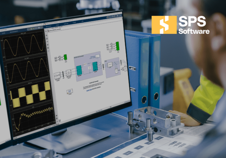
A focused set of converter types links circuit states to waveforms you measure. Start with switch based modelling so commutation and ripple are visible. Add averaged versions only after switching passes checks. That routine sharpens DC and DC/AC modelling without hiding mistakes behind control.
Freeze control at fixed duty ratio and validate energy flow first. SPS SOFTWARE helps when you need open, inspectable component models.
Keep a single probe list across all models and sweep one parameter at a time. Power balance and volt second checks will catch most errors early.
“Power balance and volt second checks will catch most errors early.”
7 converter models engineers should build first
These seven models follow a practical order. Each circuit adds one concept and needs a plotted validation signal. Build each once with ideal devices, then once with one nonideal detail.
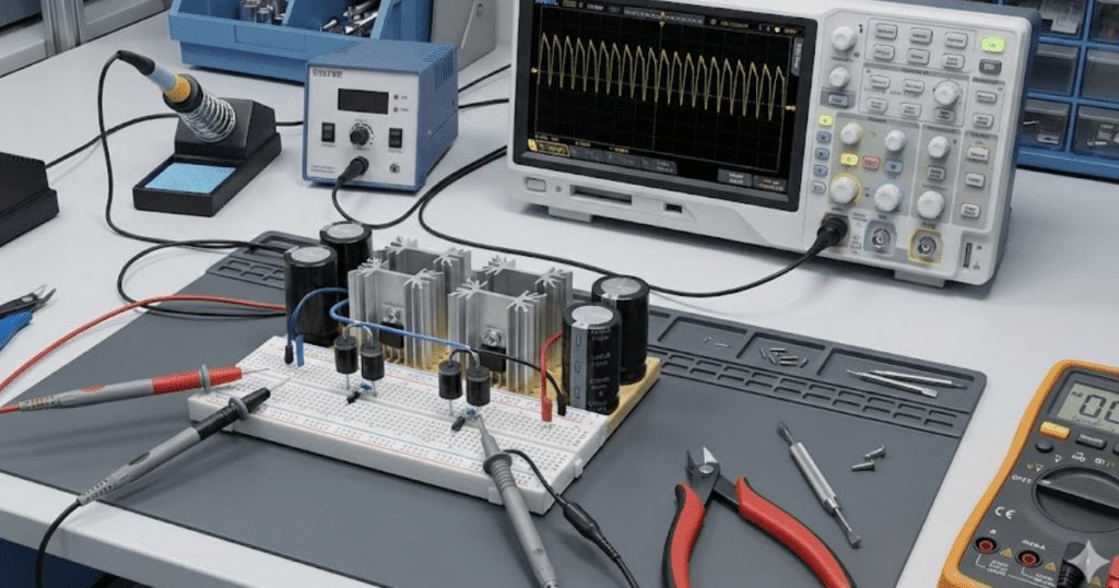
1. Uncontrolled diode rectifier as the baseline DC source
An uncontrolled diode rectifier teaches commutation without control or gate logic. Model a single phase bridge feeding a DC capacitor and a resistive load. Plot diode current pulses and DC bus voltage, then verify ripple rises with load current. Add a small source inductance, watch overlap conduction stretch pulses, and lower the bus. Measure diode conduction angle and input current crest factor so you can spot unrealistic source models. Save the DC bus ripple plot for later comparisons. This rectifier becomes the DC link you’ll reuse for inverter and motor load tests.
2. Buck converter for duty cycle and ripple understanding
A buck converter is a clean starting point for dc dc modelling because the checks are direct. Use an ideal switch, diode, inductor, capacitor, and a resistive load with a fixed duty cycle. Confirm average output voltage tracks duty times input during continuous conduction. Sweep the switching frequency and confirm that the inductor ripple current drops as the frequency rises. Step the load and confirm the output settles with a transient set by L and C. People asking how do you model DC DC converters should start here, then reuse its probes on every new topology.
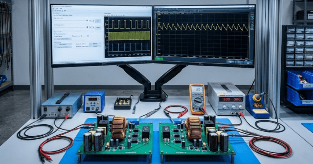
3. Boost converter for non-ideal switching behaviour
A boost converter makes nonideal switching visible because current transitions are sharp. Build the ideal circuit first, then add one detail such as diode reverse recovery. Plot switch current at turn on and compare it to inductor current, since a spike will appear once recovery is present. Plot switch voltage at turn off and confirm transient peak and ringing grow when you add stray inductance. Add a small RC snubber and confirm peak voltage drops while losses rise. This model also provides a quick test of time-step resolution at the switching frequency.
4. Buck boost converter to expose mode transitions
A buck boost converter exposes operating modes that break assumptions about polarity and conduction. Model the inverting buck boost with fixed duty and a resistive load, then track output voltage sign and inductor current. Sweep duty from 0.2 to 0.8 and verify the gain curve steepens as duty rises. Lighten the load until inductor current hits zero and discontinuous conduction appears. Compare measured gain in that mode to the continuous conduction estimate and note the mismatch. Mode detection should be based on state variables.
5. Isolated flyback converter for magnetics interaction
A flyback converter forces magnetics into your model because magnetizing inductance stores energy. Use a coupled inductor element with turns ratio, magnetizing inductance, and leakage inductance. Add a clamp so switch voltage stays bounded when leakage energy releases. Validate the primary current ramp during the on interval and the reset during the off interval. Check that magnetizing current returns to the expected level each cycle, which confirms reset is working. Plot magnetizing current peak so you can spot saturation risk. Increase leakage inductance and confirm the clamp absorbs energy.
6. Single phase voltage source inverter with ideal switches
A single phase voltage source inverter is a fast step into dc ac modelling because the switching function is easy to see. Model a full bridge on a stiff DC link and drive it with a basic PWM pattern. Run an RL load and plot output voltage, load current, and ripple near the switching frequency. Swap PWM for a square wave and compare RMS current and peak current. Add an LC output filter and confirm that switching ripple drops as phase lag increases. Teams asking how can teams set up basic dc ac models can start with this inverter plus an RL load.
“Build each once with ideal devices, then once with one nonideal detail.”
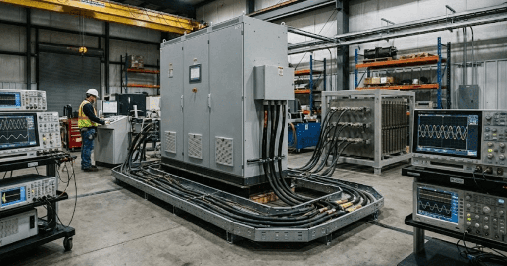
7. Three phase inverter with basic modulation and load dynamics
A three phase inverter teaches phase relationships, line to line voltages, and load dynamics in one model. Start with a balanced three phase RL load and sinusoidal modulation at a fixed modulation index. Validate balanced phase currents and confirm line to line voltages match the expected fundamental magnitude. Sweep the modulation index and confirm that the fundamental voltage scales linearly until saturation. Feed the DC link from your rectifier model and watch bus ripple print into phase voltages. Add a small load imbalance and confirm phase currents shift as expected.
Uncontrolled diode rectifier as the baseline dc source
It gives you a DC link with visible diode commutation.
Buck converter for duty cycle and ripple understanding
It teaches duty ratio and ripple checks you can trust.
Boost converter for non-ideal switching behaviour
It shows nonideal effects as stress at switching edges.
Buck boost converter to expose mode transitions
It forces you to detect operating modes from plotted states.
Isolated flyback converter for magnetics interaction
It links magnetics settings to current ramps and stress.
Single phase voltage source inverter with ideal switches
It turns DC into AC with simple modulation validation.
Three phase inverter with basic modulation and load dynamics
It ties modulation, loads, and DC bus ripple in one place.
How to choose which converter model to build next
Pick the next model based on the converter types you need to explain. Switching loss work requires switch-based modelling, while control tuning often works with an averaged power stage once waveforms are trusted. Time step limits and switching frequency set hard boundaries on model detail.
Start from the closest existing model and add one feature, such as dead time or a nonlinear load. SPS SOFTWARE fits well when you need editable models that students and senior engineers can read without translation.
Treat model building like a checklist sport. Clear probes and pass fail plots will keep reviews calm.
We use cookies to enhance your experience while using our website. If you are using our Services via a browser you can restrict, block or remove cookies through your web browser settings. We also use content and scripts from third parties that may use tracking technologies. You can selectively provide your consent below to allow such third party embeds. For complete information about the cookies we use, data we collect and how we process them, please check our Privacy Policy