
Key Takeaways
- Model fidelity should follow the study question, time window, and waveform you need to trust.
- Grid impedance, filter design, digital delay, and dc-link dynamics usually shape results more than model size alone.
- Disturbance testing is the clearest way to verify inverter control logic before hardware work starts.
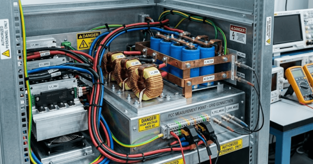
A credible three-phase inverter simulation starts with the study objective, not the switching block.
Renewable capacity additions reached almost 560 GW in 2023, and solar PV supplied about 75% of that total. That scale puts more three-phase inverters onto feeders, plant buses, and campus grids, so model quality now affects routine engineering work rather than niche studies. You will get better answers faster when model fidelity follows the grid question you need to resolve.
You are not choosing between a simple model and a detailed model in the abstract. You are choosing the minimum detail that still preserves the behaviour that matters at the point of common coupling, inside the control loops, and across the dc link. That stance keeps inverter simulation useful, readable, and easier to validate before you commit to hardware or protection settings.
“A three-phase inverter model is useful only when its detail matches the question you need answered.”
A useful three-phase inverter simulation matches the study objective

A three-phase inverter model is useful only when its detail matches the question you need answered. Grid current control, filter tuning, fault response, and feeder studies do not need the same inverter simulation, and the wrong level of detail will either waste runtime or hide the failure you need to see.
- Use a switching model when PWM ripple or dead time matters.
- Use an average model when grid trends matter more than ripple.
- Keep the filter explicit when you care about PCC current quality.
- Keep the grid source explicit when feeder strength affects stability.
- Keep digital delays explicit when control tuning feels too easy.
A 500 kW solar inverter tied to a short industrial feeder gives a clear example. If you need to verify current ripple, semiconductor gating logic, or desaturation of the current loop, a switching model is the right tool. If you need to see feeder voltage response during a 10 s irradiance drop, an average model will answer faster and with less numerical burden.
You will get more value from your inverter simulator once you write the study question as a measurable output. That usually means naming the waveform, event, and time window before you place any block. A model built that way stays focused, and it is much easier to validate when results start to look suspicious.
Switching models fit control validation with waveform detail
Switching models are the right choice when the study depends on instantaneous phase voltage, PWM ripple, dead time, sampling effects, or semiconductor commutation timing. They preserve the behaviour that average models smooth out, so they are the safest option for validating current controllers, protection logic, and filter resonance near the switching band.
A 50 kW inverter with a 10 kHz carrier and an LCL filter shows why this matters. Once you inject one grid voltage sag and inspect phase current at the point of common coupling, you can see ripple growth, saturation of the current regulator, and asymmetry from dead time. Those effects shape harmonic content and controller stress, yet they disappear if the bridge is replaced with a controlled voltage source.
You pay for that fidelity with smaller time steps and longer runs. That cost is worth it when you are testing logic transitions, overcurrent handling, or the link between modulation index and phase current. It is not worth it for a 30 s feeder disturbance where switching ripple contributes very little to the engineering answer you need.
Average models fit system studies with longer time spans
Average models are the right choice when you need correct power exchange, current loop response, dc-link energy balance, and grid interaction over longer windows. They remove switching detail and keep the dynamics that matter for system studies, which makes them far more practical for long disturbances, parameter sweeps, and feeder-level work.
Utility planning needs that efficiency because study scope keeps growing. Solar and battery storage were expected to account for 81% of new U.S. utility-scale generating capacity added in 2024. A feeder with several inverter-based resources can’t be studied effectively if every bridge is resolved at the carrier level for every scenario.
An average model is still only good when its control paths stay honest. You still need the current controller, phase-locked loop, dc-link dynamics, and current limits. If you collapse those into an ideal power source, the model becomes easy to run but hard to trust. That is where many grid studies drift away from physical behaviour, even though the waveforms look clean.
| Study question | Model choice that usually fits | What must stay explicit |
| You need phase current ripple and harmonic content at the point of common coupling. | A switching model will preserve carrier effects and timing detail. | The bridge, PWM method, dead time, and LCL filter should remain explicit. |
| You need current loop tuning during grid voltage sags or step commands. | A switching model will show how sampling and saturation alter the response. | Controller delays, limits, and measurement filtering should remain explicit. |
| You need feeder voltage and power flow over several seconds. | An average model will run faster while preserving useful inverter dynamics. | The current controller, phase-locked loop, and dc-link energy balance should remain explicit. |
| You need many parameter sweeps across line impedance or plant dispatch points. | An average model will support broader scenario coverage within practical runtime. | Grid impedance, current limits, and plant setpoints should remain explicit. |
| You need to validate protection trips caused by modulation or gating behaviour. | A switching model will expose events hidden by averaged voltage sources. | Bridge states, thresholds, and fault logic should remain explicit. |
LCL filter values set current quality at the PCC
LCL filter values determine how much switching ripple reaches the grid and where resonance appears, so they directly shape current quality at the point of common coupling. A credible model must include inverter-side inductance, grid-side inductance, filter capacitance, and damping, because each term changes the closed-loop response.
A 400 V converter tied to a 50 Hz bus makes the tradeoff obvious. If the filter capacitor is oversized, reactive current rises and the controller works harder near nominal operation. If grid-side inductance is too small, switching ripple leaks into the feeder. If damping is ignored, a neat sinusoid in simulation can turn into oscillatory current once the controller excites the resonant mode.
You should place the resonance high enough to separate it from the control bandwidth and low enough to avoid poor attenuation near the carrier. That balance matters more than any single textbook ratio. Good inverter simulation keeps filter losses and damping visible, because current quality problems are often filter problems wearing a control-system disguise.
Grid impedance assumptions set stability margins in simulation
Grid impedance sets the inverter’s effective operating condition, so a model with an ideal stiff source will overstate stability margin on weak feeders. Accurate studies need the source Thevenin equivalent, feeder impedance, transformer leakage, and local capacitance, because each part shifts resonance, controller gain, and phase margin.
A campus microgrid and a rural feeder will not stress the same inverter in the same way. The campus case might look stiff enough that a wide current-loop bandwidth seems harmless. The rural feeder can add enough inductive impedance that the same tuning produces oscillation near the phase-locked loop bandwidth. A simple impedance sweep often reveals the problem faster than another round of controller retuning.
SPS SOFTWARE fits this step well because you can inspect source, line, transformer, and control assumptions directly instead of accepting a sealed-inverter simulator. That transparency matters when results shift after one feeder parameter changes. You’re then checking physics and implementation at the same time, which is exactly where many grid-tied models fail quietly.
Control bandwidth must respect digital timing limits
Control bandwidth must be set with sampling, computation, and PWM update delays included, because digital timing removes phase margin that continuous-time tuning will hide. A model that ignores those delays will look stable on paper and then ring, overshoot, or saturate once discrete control is placed in the loop.
A common mistake appears in a current controller tuned near one-tenth of the switching frequency. The gain margin can still look comfortable until you add one sample of current measurement delay and one sample of modulation delay. That same tuning then produces noisy current, poor disturbance rejection, and a phase-locked loop that interacts badly during voltage dips.
You should model the controller exactly as it will execute, with sampling order, zero-order hold, filtering, and limit handling all included. That does not make the model harder to understand. It makes the result honest. Once those delays are visible, you’ll usually lower the target bandwidth a little and gain far better behaviour across weak-grid conditions.
Solar input models must reflect DC link behaviour
Solar input models must capture the DC-link behaviour because the inverter does not see irradiance directly. It sees source impedance, power limits, control action from maximum power point tracking, and capacitor energy. A fixed DC source can support rough control checks, but it will miss voltage sag, current limiting, and recovery behaviour during solar transients.
A grid-tied PV system during a fast cloud edge is a good test case. Panel power drops, the dc-link capacitor supplies the deficit for a short interval, and the inverter controller adjusts modulation to keep ac current within limits. If your model uses an ideal stiff dc source, none of that energy exchange appears, so the current controller looks calmer than it really is.
You do not need a full cell-level solar model for every study. You do need enough source dynamics to preserve dc-link excursions during the events you care about. That usually means a controlled dc source with realistic source resistance, power limits, capacitor value, and tracking dynamics. Once those are present, grid integration studies stop masking power-balance errors.
“Disturbance tests are the fastest way to prove that a three-phase inverter model is trustworthy.”
Disturbance tests reveal model errors before hardware work
Disturbance tests are the fastest way to prove that a three-phase inverter model is trustworthy. One model that survives step changes, voltage sags, phase jumps, current limits, and impedance variation will tell you far more than a dozen steady-state plots, because weak assumptions usually fail when the system is forced away from nominal operation.
A disciplined test set might start with a current reference step, then move to a 20% voltage sag, then repeat the same event with higher feeder impedance and a lower dc-link voltage. Those cases expose hidden couplings between the phase-locked loop, current regulator, and filter. When a model passes only under ideal grid strength, you are looking at a model that is still unfinished.
SPS SOFTWARE is most useful here when every block stays open to inspection, because good engineering judgment depends on assumptions you can trace and revise. Over time, the strongest grid-connected models are not the ones with the most detail. They are the ones tested against the right disturbances until their limits are clear and their behaviour stays consistent.