

Free Trial
Free Trial
Power Systems

Choosing simulation methods for electrical and power systems

Key Takeaways

  • Start solver selection from the study question, then match the method to the time scales and waveform detail the answer depends on.
  • Treat time step, integrator choice, and tolerances as modelling parameters, since they directly control numerical damping, stability, and what features survive in the results.
  • Build trust with disciplined validation, including consistent initial conditions, physical limit checks, and a short time step sensitivity run before interpreting converter or protection behaviour.

Choosing the right solver is how you get power system results you can trust.

Solver choice is not a software preference, it is a modelling choice that decides what physics your simulation can and cannot represent. A clean plot can still be wrong if the method cannot resolve the time scales that matter, or if numerical damping hides the behaviour you actually need to study. A standard lightning impulse used for insulation testing is 1.2/50 µs, and that single fact should settle one point early: some electrical questions live in microseconds, not seconds.

“Good solver selection starts with your study objective, then works backward to the model detail, the time step, and the numerical method that will hold accuracy where it counts.”

Speed matters, but it comes after correctness, because a faster wrong answer still costs you time when tests do not match, protections misoperate on paper, or controls look stable only because the solver blurred the dynamics. Treat the solver and its settings as part of your model, document them, and you will get results that hold up under review.

Define common power system solvers used in electrical studies
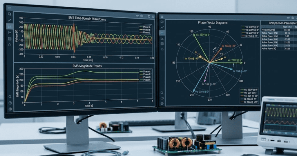
Power system solvers fall into a few families that each simplify the physics differently. Algebraic solvers handle steady state power flow and short circuit calculations without time stepping. Phasor and RMS time domain solvers step electromechanical dynamics using averaged network behaviour. EMT solvers step the full electrical waveforms, so switching, saturation, and fast protection effects show up directly.

Those families also differ in how they solve equations at each time step. Power flow typically uses Newton style iteration on algebraic equations, while EMT and RMS solvers integrate differential algebraic equations that combine network constraints with device dynamics. Fixed time step EMT focuses on repeatable waveform accuracy, while variable time step RMS often focuses on long runs with acceptable dynamic error. Solver terms like “explicit,” “implicit,” “trapezoidal,” and “backward Euler” describe how the integrator behaves when the system has fast and slow dynamics mixed together.

A practical way to keep this straight is to ask what your model states really represent. RMS and phasor models usually represent fundamental frequency magnitudes and angles, so they will not show PWM ripple or subcycle peaks that drive some protections. EMT models represent instantaneous voltages and currents, which is why they catch commutation overlap, diode recovery effects, and wave propagation effects when line detail matters. Once you pick the solver family, the rest of the setup is not “tuning,” it is matching the numerics to the physics you chose to represent.

Match study objectives to EMT and phasor domain simulation

EMT simulation is the right fit when the answer depends on waveform detail, fast switching, or subcycle interactions between the network and devices. Phasor and RMS simulation is the right fit when the answer depends on slower dynamics, steady state limits, or system level behaviour over many cycles. The method you choose sets a ceiling on the fastest phenomenon you can trust. That ceiling matters more than the run time.

A concrete way to choose is to frame your question as “what must be time resolved to answer this.” Consider a 13.8 kV industrial feeder with a VFD front end, a capacitor bank, and an overcurrent relay set near a sensitive process load. If you need to see capacitor inrush peaks, diode bridge commutation notches, and relay pickup on a distorted current, EMT will be the only method that shows those details without heavy assumptions. If you only need the post-event voltage recovery trend across tens of seconds after a motor restart, a phasor or RMS study will answer faster with less model detail.

What you need to learnMethod that usually fitsWhat will decide accuracy most
Steady state voltages, losses, and equipment loadingPower flow with an algebraic network solverModel data quality and consistent base values will matter more than solver settings
Generator angle and frequency response over secondsPhasor or RMS electromechanical simulationMachine, governor, and exciter models plus event timing will dominate results
Converter control interactions and switching related distortionsEMT time domain simulationTime step, switch model detail, and control sampling will set what you can trust
Protection pickup that depends on subcycle peaks or distortionEMT or waveform based protection modellingAnti alias filtering, measurement windows, and integration method stability will matter
Long feeder voltage profiles across many load changesQuasi static time series using steady state solvesLoad models, tap logic, and event sequencing will dominate, not microsecond detail
Travelling waves and surge propagation along long conductorsEMT with distributed line representationPropagation effects scale with the speed of light at 299,792,458 m/s, so time resolution must respect those delays

Once the objective is clear, mixed workflows become easier to manage. Start with a simpler method to set initial conditions and sanity check operating points, then move to EMT only where the physics needs it. A solver does not fix missing model detail, and extra detail does not rescue a solver that cannot represent the behaviour your question depends on. Pick the method that matches the question, then set the numerics to protect that choice.

Use time step and integration settings to control accuracy

Time step and integration method control numerical error, numerical damping, and stability, so they directly shape what you will believe from a plot. A time step that is too large will smooth peaks and distort phase, even if the simulation “runs fine.” A method that is too aggressive on damping will hide oscillations that matter for control or protection. The right settings come from the fastest dynamics you must resolve, not from defaults.

Fixed step EMT usually works best when you set the step from switching frequency, the smallest L and C time constants, and the fastest control sampling in the model. A common engineering check is to keep enough points per switching period that switching edges do not collapse into one or two samples, then confirm key quantities do not change much if you halve the time step. Trapezoidal integration will preserve waveform detail well, but it can show numerical ringing if discontinuities are harsh. Backward Euler will damp high frequency content, which can help stability but can also hide the very ripple you needed to see.

  • Set a maximum time step that is tied to your fastest physical time constant
  • Check integrator choice against your need for ripple detail versus damping
  • Align controller sample times with the simulation step to avoid timing drift
  • Set nonlinear solver tolerances so currents and voltages converge tightly
  • Re run a short window at a smaller step to confirm key results hold

Accuracy problems often look like “weird physics,” but the cause is numerical. Spikes at switching instants can be time step artefacts, while missing overshoot can be numerical damping. Event handling also matters, since breaker operations and limiter activations can create discontinuities that stress the integrator. When you treat the time step as a modelling parameter and not a performance knob, you will avoid long loops of trial and error.

Handle stiff networks and nonlinear devices without convergence issues

Stiff systems mix very fast and much slower dynamics, and that mix can cause explicit methods to become unstable or force impractically small steps. Nonlinear devices add iterative solves inside each step, so convergence settings become part of accuracy and not just a way to stop warnings. Ideal switches, saturating magnetics, and hard limits create discontinuities that make iterations struggle. Stable results come from a solver that matches stiffness and a model that avoids impossible idealizations.

Practical fixes usually start with the device models. Parasitic resistances, snubbers, and realistic source impedance remove infinite di or dv demands that no numerical method can satisfy. Smoother limiter functions often behave better than hard clipping, since they reduce sudden Jacobian changes during Newton iterations. Consistent initial conditions also matter, because a solver that starts far from a feasible operating point will waste iterations and can land in nonphysical states.

Tool transparency helps here because you can see what equation is actually failing when convergence breaks. SPS SOFTWARE is often used in teaching and research settings for this reason, since editable component models make it easier to spot where an “ideal” assumption created stiffness or where a limiter created an algebraic loop. Once the model is physically reasonable, implicit integration and sensible tolerances will do their job.

“Convergence success is not luck, it is the result of model realism and numerical alignment.”

Validate results using initial conditions, limits, and sanity checks

Validation is the step that proves your solver choice did not hide a modelling error. Initial conditions must match the steady state you intend, or the simulation will spend its first cycles correcting a mismatch you never meant to study. Physical limits must hold, such as capacitor voltage continuity and inductor current continuity across switching events. Basic sanity checks will catch unit errors, sign mistakes, and impossible setpoints before you trust any deeper insight.

Start with the simplest checks that do not require another tool. Confirm voltages and currents match expected magnitudes at steady state, confirm power balances are sensible, and confirm device states align with control logic. Check that protection elements see the same measurements you think you modelled, including any filtering and measurement windows. A short run with a reduced time step is also a strong check, because large differences signal numerical sensitivity that you must address before you interpret fine detail.

Limits and invariants provide another layer of confidence. Saturation should clip flux or current where the model says it should, not where the integrator can tolerate it. Energy stored in inductors and capacitors should not grow without a source, and damping should not appear from nowhere. When validation is disciplined, solver choice becomes a controlled engineering variable instead of a hidden source of uncertainty.

Avoid common solver selection mistakes in converters and protection studies

Most solver mistakes come from asking a waveform question with a non-waveform method, or from using an EMT method with settings that cannot resolve the behaviour you care about. Converter models amplify this problem because switching, control sampling, and nonlinear limits all sit close together in time. Protection models amplify it again because pickup and timing can depend on peaks, distortion, and measurement windows. You will get better outcomes when you treat solver settings as part of the protection or converter design, not as an afterthought.

Phasor studies often fail for converter and protection work when key triggers depend on distortion, DC offsets, or subcycle features. EMT studies fail when the time step is too large, when the integrator adds damping that hides ripple, or when ideal device models create discontinuities that force convergence shortcuts. Another common issue is mixing discrete logic with a variable time step without checking event timing, since timing drift can shift relay operations or control state changes. Clear alignment between sampling, switching, and integration timing keeps those errors from creeping in.

The best long term habit is to write down what must be resolved, then pick the simplest method that still resolves it cleanly. A short pilot run that checks convergence, time step sensitivity, and measurement behaviour will save more time than chasing “weird” plots late in a project. Teams that work in SPS SOFTWARE often formalize this as part of their model setup, since transparent equations and editable models make solver assumptions visible and reviewable. That discipline, more than any single solver setting, is what turns simulation from a nice picture into engineering evidence.

Simulation

Supporting reproducible research with physics-based simulation models

Key Takeaways

  • Reproducible EMT research starts when you treat the simulation run as a complete, rerunnable record that includes the model, numerics, inputs, and tool versions.
  • Physics-based model transparency matters as much as results, because readers need to inspect equations, assumptions, and control logic to trust that the same study is being rerun.
  • Most repeatability failures come from small, undocumented choices such as time step, event timing, initialization, and post-processing, so disciplined run manifests and portable study packaging should be standard practice.

Reproducible simulation research fails most often when authors treat a simulator run as a screenshot instead of a record you can rerun. A large survey found 70% of researchers had tried and failed to reproduce another scientist’s experiments. EMT research carries extra risk because small numerical and modelling choices can shift waveforms, trip logic, and protection outcomes.

“You can make EMT power system results repeatable when you publish the model, the numerics, and the run conditions as a single package.”

The practical stance is simple: reproducibility is a design requirement for your study, not a clean-up task after you’ve written results. Physics-based modelling makes that achievable because equations, parameters, and assumptions can be inspected and challenged. Your job is to keep every hidden decision visible, from solver tolerances to initial conditions, so a reviewer or lab partner can rerun the study and reach the same technical conclusions.

Define reproducible simulation research in EMT power system studies

Reproducible EMT research means an independent reader can run your simulation model and obtain the same key plots and metrics within a stated tolerance. It includes the full model, all inputs, and the numerical settings used to generate results. It also includes tool versions and any external scripts. It is stricter than claiming similar behaviour.

For EMT work, “same result” should be defined in engineering terms, not aesthetics. If your claim depends on peak current, DC link ripple, PLL stability, or protection pickup time, you need a numeric acceptance band for those outputs. That band should reflect numerical noise you expect from different machines, not the spread you get from undocumented parameter choices.

It also helps to separate three levels of repeatability so your readers know what to expect. Repeatable runs on the same computer test basic run control. Reproducing on a different computer tests tool versioning, floating point differences, and hidden dependencies. Reproducing in another simulator tests modelling assumptions, and that requires even clearer documentation of physics-based equations and control logic.

Specify model transparency requirements for physics-based power system modelling

Transparent physics-based models expose equations, parameters, and component limits so others can inspect what your study actually simulates. You should be able to trace any plotted waveform back to a component model and a parameter value. Control blocks must be readable, not compiled into opaque artefacts. If a value is tuned, the tuning target must be stated.

Start with a tight “model contract” that defines what is inside the scope and what is not. If you use an averaged converter model, state the switching details you removed and why that is acceptable for your claim. If you include detailed switching, state how you represent device losses, dead time, and saturation. Readers do not need every intermediate note, but they do need every assumption that changes physics.

Transparency also includes naming and structure. Consistent signal names, clear subsystem boundaries, and readable units reduce the risk that another researcher wires something incorrectly and blames the tool. When a model is clear enough for a graduate student to audit, it is usually clear enough for a reviewer to trust.

Control numerical settings that most often break reproducibility

EMT reproducibility breaks when solver choices, time step, interpolation, and event handling are treated as defaults. Time step and tolerances directly affect switching ripple, control stability margins, and protection timing. Event timing rules, such as breaker operation and fault insertion, must be specified precisely. You should publish these settings as part of the study definition, not as simulator trivia.

Consider a grid fault study on a 2 MW inverter model where your claim depends on the first 10 ms of current limiting. A fixed time step of 5 µs can show a different peak and a different limiter activation instant than 20 µs, even with identical controller gains, because sampling, discretization, and switch event alignment shift. If the paper reports only the controller diagram and omits the numerical settings, another lab can “replicate” the model and still miss your headline result.

Set explicit rules for how you choose numerics. Start with a time step justified by the fastest dynamics you keep, then confirm key outputs are stable under a smaller step. State any filters or decimation used for plots so readers do not confuse display smoothing with physical damping. When your results depend on threshold crossings, record the detection method and the comparison tolerance.

Record inputs, initial conditions, and solver versions consistently

Repeatable EMT studies require a complete run record that captures every input, initial state, and tool version used. Initial conditions matter because controls, machine states, and network voltages can settle into different trajectories. Versioning matters because solvers, libraries, and numerical fixes change behaviour. If you can’t recreate your own figures six months later, nobody else will.

Use a run manifest that travels with the model and gets updated every time you regenerate results. Treat it like a lab notebook entry with strict fields, not free text. When you work with teams, a manifest becomes the shared reference that prevents quiet drift between “the model” and “the results.”

  • Simulation tool name, exact version, and operating system details
  • Solver type, fixed or variable step, time step, and error tolerances
  • All input files with checksums and a single source of parameter values
  • Initial condition method, including any power flow or steady-state pre-run
  • Event schedule with timestamps for faults, switching, and controller mode changes

The same discipline applies to scripts used for plotting and post-processing. If a plot uses windowing, resampling, or filtering, record the settings and the code version. A clean run record turns review comments into quick reruns instead of weeks of reconstruction.

Package and share EMT studies so others can rerun

“Sharing for reproducibility means shipping a runnable bundle, not a diagram and a parameter table.”

A complete package includes model files, the run manifest, input datasets, and the plotting scripts that generate published figures. File paths must be relative and portable so the project opens on a new machine without manual repair. Your goal is a single command or click that reproduces the outputs you cite.

Packaging works best when you separate editable source from generated artefacts. Keep source models, parameter sets, and scripts under version control, and store generated plots in a results folder tied to a specific commit. Archive the exact run bundle associated with a submission so later edits do not overwrite the provenance of published figures.

Some teams standardize this workflow inside SPS SOFTWARE because open, editable component models and clear parameterization make it easier to bundle what matters for reruns. The tool choice matters less than the habit: if the recipient cannot inspect and execute what you used, the study cannot be reproduced.

Detect common reporting gaps that block repeatable results

The fastest way to improve reproducibility is to look for gaps reviewers repeatedly hit: missing numerics, missing initial conditions, and missing event definitions. These omissions are not minor, because EMT outputs can shift with tiny differences. A separate survey finding showed 52% of researchers agree there is a significant reproducibility crisis. That pattern matches what power system reviewers see when simulation results can’t be rerun.

A simple self-test catches most issues before submission. Another person on your team should be able to clone the study bundle, run it on a clean machine, and regenerate every figure without asking you questions. If they need an email thread to find solver settings, a parameter file, or the exact event timing, the paper is not ready for scrutiny.

Reproducibility checkpointWhat you must recordWhat a rerunner can verify quickly
Model transparencyEditable equations, readable control logic, and parameter sourcesEvery plotted signal traces to a model element and value
Numerical configurationSolver type, step size, tolerances, and event timing rulesKey peaks and timing match within your stated tolerance band
Initial conditionsPre-run method, power flow assumptions, and state initialization filesStartup transients and steady-state values align with reported baselines
Inputs and disturbancesParameter sets, external data, and a timestamped event scheduleFaults, switching, and mode changes occur at identical times
Provenance and packagingTool versions, run manifest, and portable file structureThe study runs on a clean machine without path fixes

Good reproducibility feels strict, but it pays off in calmer review cycles and cleaner internal handoffs. Teams that treat modelling as a publishable artifact, not a personal workspace, build credibility that accumulates over time. SPS SOFTWARE fits best when you want that discipline supported by transparent, inspectable physics-based models, yet the outcome still depends on your run records and packaging habits.

Electrical Engineering

10 Best practices for organizing electrical system models

Key Takeaways

  • Set scope and study intent first so model fidelity, solver choices, and outputs stay consistent with the questions you need answered.
  • Use strict conventions for naming, units, signal flow, and subsystem ports so large power system models stay readable and reusable across teams and labs.
  • Protect repeatability with shared libraries, small test harnesses, centralized scaling, and stored initialization and solver settings, then keep quality steady with a simple review checklist.

You can keep large electrical models clear, reusable, and testable with a few consistent structure rules.

“Good organization removes the hidden work that slows teams down, like hunting for parameters, guessing signal meaning, or fixing the same wiring mistake in five places.”

It also makes results easier to trust because assumptions stay visible instead of getting buried inside deep subsystems.

Model size is not the main problem; inconsistency is. A well-structured EMT or phasor model can grow for years without becoming fragile, as long as you treat model structure like an engineering interface and not just a drawing exercise.

Set scope and study intent for large power system models

The cleanest model organization starts with a strict scope statement that defines what questions the model must answer and what it will ignore. You should lock down study type, event set, accuracy needs, and the outputs you will use to judge success. That scope then sets the right level of switching detail, control bandwidth, and network size.

Write scope in terms of test cases and measurements, not in terms of blocks you plan to draw. Identify the boundary buses, the measurement points, and the disturbance types you will apply. Keep a short list of non-goals so you do not accidentally mix studies, such as protection timing validation and converter loss estimation, inside the same baseline model.

Standardize naming, units, and signal flow conventions early

Consistent naming and units turn a complex diagram into something you can scan and verify. Signal names should tell you what the value represents, its reference frame, and its units. Port direction should stay consistent across the whole model so you do not need to read every wire to understand causality.

Write these conventions down once and apply them to every new subsystem and library block. A small amount of up-front discipline prevents confusion later when multiple people touch the same models across labs, projects, or course terms.

  • Use one bus naming pattern across all voltage levels
  • Add unit hints in signal names such as kV, A, pu
  • Keep control signals flowing left to right across diagrams
  • Reserve one colour scheme for measurement and logging paths
  • Document reference directions for power, current, and torque

10 best practices for organizing electrical system models

These practices focus on readability first, then reuse and testability. Each one reduces a specific failure mode such as duplicated logic, hidden scaling, or solver changes that silently alter results. Apply them in order when you refactor an existing model, or as a checklist when you start a new one.

1. Split models by voltage level and functional purpose

Partition the model so each layer has one clear job, such as transmission, medium voltage feeders, or low voltage converter connection. Keep each partition small enough that you can validate it with focused tests. Tie partitions together through defined buses and interfaces, not ad hoc wiring. This keeps changes local when a study scope shifts.

2. Keep top diagrams shallow with clear left to right flow

Use the top level to show structure, not detail. A shallow diagram with a consistent left to right signal flow lets you understand the full system in minutes. Group blocks so the power path is obvious and the control path is separate. Push detail down into subsystems so the top does not become a wiring map.

3. Use subsystems to hide detail and expose key ports

Subsystem boundaries should match engineering boundaries, such as a converter, a feeder segment, or a protection relay function. Expose only the ports needed to connect and test that subsystem. Keep internal measurement, scaling, and filter details inside the subsystem so the interface stays stable. Treat subsystem ports like a contract you do not casually break.

4. Separate EMT switching detail from average value sections

Mixing switching models and average value models without clear boundaries makes results hard to interpret. Keep high-frequency switching detail in dedicated areas so time step and solver choices remain obvious. Place average value equivalents in separate subsystems with the same external ports where possible. This supports quick study swaps without rebuilding the diagram.

5. Put reusable components in a shared library structure

Reusable models belong in libraries, not copied across projects. Library blocks keep fixes and improvements consistent, and they reduce the risk of silent divergence between similar subsystems. Keep libraries organized by function, such as machines, converters, networks, and protection. Add short descriptions so new users choose the right block on the first try.

6. Centralize base values, per unit scaling, and unit checks

Scaling mistakes often look like control instability or network faults, so treat unit management as a first-class design task. Store base values and per-unit conversion in one place and reference them everywhere. Add simple unit checks on key signals so errors show up early. Keep conversions close to interfaces, not scattered across the diagram.

7. Use consistent parameter sets with defaults and limits

Parameter sprawl makes models fragile because small edits change behaviour in unexpected ways. Group related parameters into structured sets and keep defaults close to typical studies. Add limits and sanity checks to catch impossible values before simulation starts. Maintain a clear separation between physical parameters and tuning parameters.

8. Separate power network, controls, protection, and measurements

Separate domains so you can review and test each one without distraction. Keep the power network focused on impedances, sources, and switching, while controls and protection stay in their own areas. Route measurements through a dedicated logging layer so instrumentation does not clutter functional logic. This structure also makes it easier to compare control versions against the same network baseline.

9. Add small test harness models for each major subsystem

A test harness gives you a fast way to validate a subsystem without loading the full system model. The harness should provide boundary conditions, reference inputs, and checks for expected outputs. A simple harness might feed a converter model with a DC source, a grid Thevenin equivalent, and a step in current reference while logging DC link ripple and line current distortion. Keep harnesses versioned beside the subsystem so updates stay linked.

10. Store solver settings, initialization, and annotations with models

Solver changes can shift results even when the diagram looks identical, so settings must be treated as part of the model. Keep initialization steps close to the subsystem they apply to, and write annotations that state assumptions and limitations. Use consistent initial conditions so test cases are repeatable. Capture any required configuration so someone else can run the model without guessing.

“Subsystem boundaries should match engineering boundaries, such as a converter, a feeder segment, or a protection relay function.”

PracticeMain takeaway
1. Split models by voltage level and functional purposeClear partitions keep changes local and verification focused.
2. Keep top diagrams shallow with clear left to right flowTop levels should explain structure quickly, not show wiring detail.
3. Use subsystems to hide detail and expose key portsStable interfaces reduce rework when internals change.
4. Separate EMT switching detail from average value sectionsClear modelling boundaries prevent hidden solver and fidelity conflicts.
5. Put reusable components in a shared library structureLibraries prevent copied blocks from silently diverging across projects.
6. Centralize base values, per unit scaling, and unit checksCentral scaling avoids unit errors that look like system instability.
7. Use consistent parameter sets with defaults and limitsStructured parameters keep behaviour predictable and reviews faster.
8. Separate power network, controls, protection, and measurementsDomain separation makes testing and troubleshooting more direct.
9. Add small test harness models for each major subsystemHarnesses keep subsystem validation quick and repeatable.
10. Store solver settings, initialization, and annotations with modelsRepeatable runs require solver and initialization to travel with the model.

Design subsystem interfaces for reusable simulation models and labs

Reusable simulation models depend on interface discipline more than clever internal implementation. Define what each subsystem accepts and produces, then keep that interface stable across versions. Use clear port names, documented signal units, and explicit reference directions so connections stay correct even when the model is reused in another system.

Interface discipline also supports teaching and team work because students and new engineers can connect blocks without guessing intent. SPS SOFTWARE users often get the best results when subsystems behave like well-defined components, with parameter sets that travel cleanly between lab exercises and research studies. Keep optional features behind parameters, not separate ad hoc copies of the same block.

Use review checklists and model metrics to guide refactors

Refactoring works best when you review structure the same way you review protection settings or control gains. Use a short checklist that flags duplicated logic, hidden scaling, inconsistent naming, and unclear subsystem boundaries. Track a few simple metrics, such as number of duplicate blocks removed, number of interface ports simplified, and count of unit conversions pushed to boundaries.

Good model organization is visible in daily work because debugging becomes faster and test cases become easier to repeat. SPS SOFTWARE fits well when you want transparent, physics-based modelling where the structure stays readable as complexity grows. Treat organization as part of engineering quality, and the model will stay useful long after the first study is finished.

Electrical Engineering

Modelling faults and switching events in electrical networks

Key Takeaways

  • Start with a measurable study goal, then match model detail to the specific transient or duty you must verify.
  • Use EMT only when waveform timing and switching physics will change the decision, and use RMS for broad screening and longer time windows.
  • Protect accuracy first with disciplined event timing, fault impedance, and boundary equivalents, then improve speed through focused network reduction and time step control.

Accurate fault and switching models will give you transient results you can trust.

Fault studies only pay off when the model matches the event you’re trying to understand, not just the one you can simulate quickly. Power interruptions are costly enough that avoidable modelling errors matter, with a Lawrence Berkeley National Laboratory study estimating about $44 billion per year in outage costs for U.S. electricity customers. That kind of impact is why disciplined fault and switching event modelling is worth the effort.

“The practical stance is simple: start with the study goal, pick the lightest model that can still answer it, and only then optimize speed.”

Breaker operations, fault impedance, and protection timing sit right on the line between “good enough” and “misleading.” Getting those details right will save you from confident looking plots that point to the wrong engineering action.

Start with the fault and switching study goals

Define the goal in terms of a measurable outcome and a pass fail check. You should know if you’re validating protection operation, checking equipment duty, or confirming ride through behaviour. Each goal implies a different time window, network detail, and output set. Clear goals stop you from overbuilding models that run slowly but answer nothing.

Lock down a minimum set of study inputs before you touch model detail. This keeps the team aligned on what must be accurate and what can be simplified. It also makes reruns and reviews much easier, since you can see what changed and why. These five items are usually enough to start well:

  • Define the fault types and switching events you must represent
  • Set the exact event times and required sequencing constraints
  • Choose the outputs that decide pass fail for your study
  • Confirm the source strength assumptions at the study boundary
  • Agree on acceptable run time and acceptable error bands

Goal clarity also forces a useful question early: do you need waveform detail, or do you need system level trends. If your answer is “both,” split the work into phases, since one model rarely serves both needs well. That split is also where most simulation time savings come from, without cutting corners on the part that matters.

Choose EMT or RMS simulation based on transient detail

EMT simulation is the right choice when switching transients, harmonics, and fast control interactions matter. RMS simulation is the right choice when you mainly need phasor magnitude and angle behaviour over longer periods. The selection should follow the time scale of the phenomenon you’re studying. Picking EMT for every case will slow you down and still won’t fix poor event modelling.

EMT uses small time steps to resolve high frequency content, so it captures breaker prestrike, transformer inrush, and converter switching effects when model detail supports it. RMS assumes sinusoidal steady behaviour within each step, so it suits load flow, slower voltage recovery, and stability style studies. A common workflow uses EMT for the first tens or hundreds of milliseconds, then shifts to RMS once the fast energy exchange settles. That handoff only works if you define what “settled” means in your outputs.

Study needEMT simulation tends to fitRMS simulation tends to fit
Breaker or switch transient dutyCaptures steep recovery voltage and current chopping effectsMisses high frequency detail that sets peak stress
Protection timing based on instantaneous quantitiesMatches time domain pickup and filtering behaviourNeeds careful approximations for fast elements
Long duration voltage recovery and stabilityRuns slowly and can hide trends in heavy detailRuns fast and highlights system level trajectory
Converter and harmonic interactionsRepresents switching ripple and control coupling if modelledOften reduces converters to averaged behaviour
Study turnaround time for many contingenciesBecomes costly unless the network is reduced carefullySupports broad screening with reasonable computation time

Tooling matters less than model transparency when you need to justify results. SPS SOFTWARE supports physics-based EMT and RMS modelling where you can inspect and edit component behaviour, which helps teams stay consistent across study types. That consistency is a practical advantage when results must survive review and reuse. It also helps you avoid hidden assumptions that only show up after you’ve spent hours on runs.

Model short circuit faults with location impedance and timing

Fault simulation in power systems starts with three choices that control most outcomes: fault type, fault impedance, and the exact time of inception and clearing. Location matters because network impedance changes with distance and topology. Timing matters because the voltage angle at inception sets the first peak. If those inputs are vague, the results will be vague too.

Most studies should prioritize single line to ground representation, since that fault class dominates many systems. Single line to ground faults are often cited as about 70% of power system faults in instructional protection material. That statistic is useful because it tells you where modelling effort will pay back first. It also supports using multiple impedance values, since “solid” and “resistive” ground faults stress different parts of the system.

Fault impedance should reflect the physical path, not just a convenient number. Arc resistance, tower footing, cable sheath return, and contact surface conditions all shift current magnitude and DC offset decay. Clearing time should be tied to the protection and breaker sequence you expect, including any intentional delay. If the study target is equipment duty, you also need to model how the network upstream is represented, since a weak Thevenin source can cut peaks sharply.

Represent breaker and switch operations with realistic contact behaviour

Breaker modelling should match the stress you’re checking, not just the logic you’re implementing. An ideal switch that toggles open and closed at a time instant will often be fine for phasor studies. EMT fault analysis needs more care, since contact parting, arc extinction, and restrike can shape the first few milliseconds. Switching event modelling becomes misleading when the breaker is treated as perfectly clean.

Start with the simplest representation that still captures the key quantities. Controlled switching needs a model that respects current zero crossing, since mechanical opening time and pole scatter affect interruption. Transformer energization studies need prestrike behaviour to get inrush right, since the effective closing angle is rarely the commanded time. Capacitor bank switching can need preinsertion elements or damping if you’re evaluating transient overvoltage.

Contact behaviour also ties directly to how you align events in the simulation. A breaker command time is not the same as contact separation time, and a trip signal is not the same as current interruption. Model event delays explicitly, keep them consistent across phases, and document them as parameters. That habit makes sensitivity checks easier when someone questions why one run looks different from another.

Handle protection logic reclosing and transient fault clearing

Protection and reclosing logic must be represented as a sequence of measurements, decisions, and actuator delays, not just a single open command. Transient faults clear only if arc extinction and deionization are plausible within the dead time. If you skip these mechanics, you can accidentally “prove” a scheme works when it depends on timing that the field will never achieve. You’ll get the most value when protection and breaker models share the same timing assumptions.

Consider an overhead 25 kV feeder with a recloser protecting a lateral. A line to ground flashover occurs at 0.12 s with 15 ohms of fault resistance, the relay asserts a trip after 25 ms of filtering, and contacts part 35 ms later with a 400 ms dead time before reclosing. The simulated voltage recovery and the second close current will look completely different if the dead time is 200 ms, or if you assume instantaneous interruption at the trip time. That single timing chain often decides if the transient fault clears cleanly or becomes a sustained event.

Accurate relay behaviour does not require modelling every internal block, but it does require matching what the relay “sees.” Filtering, phasor estimation window length, and CT saturation can all shift operate time and element security. Align those assumptions with the study goal, then check sensitivity to the timing parameters you can’t control tightly. When results hinge on a few milliseconds, the right response is usually better modelling discipline, not more optimism.

Improve simulation speed while keeping switching transients accurate

Simulation speed improves most when you reduce unnecessary bandwidth and unnecessary network detail, while keeping the event physics intact. EMT runs slow mainly because of small time steps and large state counts. You can shorten runs by focusing high fidelity only around the faulted area and the switching devices that drive the transient.

“Speed work should never start until you know which waveforms must remain trustworthy.”

Network reduction is often the safest first move. Replace distant parts of the grid with Thevenin equivalents that match short circuit strength and X to R ratio over the frequency range you care about. Keep transformers, cables, and reactors that shape transient voltage and current near the switching point. Set a time window that ends once the quantity of interest settles, since modelling an extra second at EMT resolution can waste most of your runtime.

Time step selection deserves equal care. Too large a step will smooth peaks, distort interruption, and shift protection timing. Too small a step will bury you in computation with little gain. A good practice is to run one high-fidelity baseline case, then adjust reductions and step size until key peaks and timings stay within your acceptance bands.

Validate results and avoid common fault modelling mistakes

Validation means checking that the simulation behaves like a power system, not like a plot generator. You should verify that pre-fault load flow and voltages match expectations, and that fault current levels are consistent with short circuit calculations. Energy storage elements must show physically reasonable exchange, especially during switching. If those checks fail, speed and detail choices won’t rescue the study.

Common mistakes tend to cluster around timing and boundaries. Trip time is often confused with contact separation, and close time is often confused with effective electrical closing angle. Source equivalents get reused across cases even when topology changes, which quietly shifts fault level and DC offset. Fault impedance is set to zero for convenience, then the results are used to justify protection settings that will never see that condition.

Good fault simulation power systems work is mostly disciplined repetition, not heroic modelling. You’ll get better outcomes when every case has the same event definitions, parameter naming, and validation checks, since differences then become meaningful rather than accidental. SPS SOFTWARE fits well when you need transparent models that can be inspected and controlled, since trust builds from what you can explain, not what you can run. The strongest studies finish with a simple judgment: if the result cannot be defended from inputs to waveforms, it is not ready to guide an engineering choice.

Uncategorized

Managing switching detail and timestep selection in converter models

Key Takeaways

  • Pick switching detail based on the decision you need to make, since ripple, peaks, and harmonics only become trustworthy when the model actually represents switching behaviour.
  • Choose timestep from the fastest behaviour you will interpret, then prove it through convergence checks so peak stress, ripple, and losses do not depend on step size.
  • Control runtime through targeted detail and careful output sampling, since coarse storage or misaligned switching events can hide aliasing and create false low-frequency effects.

Switching models create the waveforms you see on a bench, but they also create the hardest numerical problem you’ll give a simulator: sharp edges, wideband harmonics, and stiff energy storage. Sampling theory sets the tone here, since representing a signal without aliasing requires a sample rate above 2x the highest frequency of interest. A timestep choice is simply that sampling choice expressed in seconds.

Averaged models and switching models are not competing “accuracy levels.” They are different instruments. The most reliable results come from pairing the model detail to your study question, then selecting a timestep that resolves the fastest behaviour you care about, not the fastest behaviour that exists anywhere in the schematic.

 “Your converter simulation will only be as trustworthy as your switching detail and timestep.”

Choose switching or averaged converter models based on study goals

Use a switching model when you need ripple, peaks, harmonic content, device stress, or detailed interaction with protection and parasitics. Use an averaged model when you need control behaviour, steady-state operating points, slow transients, or system studies where switching ripple will only obscure the answer. The right choice is the one that matches the decision you need to make.

Switching models represent the discrete on-off states of semiconductor devices, so they naturally produce PWM ripple, diode recovery effects, and high dv dt and di dt edges. That fidelity matters for capacitor ripple current, transformer flux swing, filter damping, and controller sampling effects, because these depend on instantaneous waveforms and not just their averages. It also matters any time you need peak values rather than rms, since peaks often set thermal and reliability limits.

Averaged models replace the switch network with a controlled source or equivalent duty-cycle dependent relation. That removes the carrier frequency content, which usually makes the simulation stable at much larger timesteps and lets you study longer windows. If your goal is grid level interaction, droop response, start-up sequencing, or tuning a loop bandwidth, an averaged model will answer faster with fewer numerical traps.

Identify what switching detail changes in key waveforms and losses

Switching detail changes what your model treats as “real” in the electrical sense: ripple, harmonics, and peak stresses become explicit signals instead of being implied. That directly affects predicted conduction loss, switching loss, ripple heating in magnetics and capacitors, and any control logic that depends on sampled currents and voltages. Averaging removes the carrier and reshapes these outcomes.

Ripple is not cosmetic. A small change in ripple current can move a capacitor from acceptable temperature rise to chronic overheating, and the same ripple can excite resonances in filters and cables that never show up in an averaged model. Harmonics also matter outside of power quality reporting, since compliance work often spans far above the fundamental and even above the switching frequency through its harmonics.

One useful reference point is conducted emissions practice, since disturbance limits are assessed from 150 kHz to 30 MHz in CISPR 11. A switching model will generate content that reaches into that range if your edges are fast enough or your parasitics are represented, and your timestep choice will decide which part of that spectrum is credible. If you smooth the switching detail too aggressively, you will still get a “clean” waveform, but it will be clean for the wrong reason.

Set simulation timestep from switching frequency and control bandwidth

A practical timestep starts from the fastest behaviour you need to resolve, then adds margin so numerical integration does not smear edges or shift phases. For switching models, that behaviour is usually the PWM carrier period, dead time, and any resonant ringing you intend to keep. For averaged models, the fastest behaviour is usually the control bandwidth and the dominant plant poles.

Consider a 20 kHz PWM converter where you care about inductor ripple current and switch peak current during transients. The switching period is 50 µs, so a timestep around 0.5 µs gives 100 points per period and usually captures ripple shape without turning every edge into a stair-step. If your model includes 200 ns dead time or a few MHz ringing that you want to see, that timestep is no longer adequate, and the timestep must shrink until those features stop shifting as you refine it.

Control adds a second constraint. A digital controller with a kHz scale bandwidth can look stable with a coarse timestep and still be wrong in phase margin once sampling and modulation delays are represented. The safest workflow is to tie timestep to the highest frequency you will interpret in plots or metrics, then verify convergence by halving the timestep and checking if key outcomes, such as ripple amplitude and peak device current, settle to a consistent value.

What you need from the simulationModel detail that supports that needTimestep checkpoint that keeps results believable
Loop tuning and slow transients over secondsAveraged converter with explicit control and limitsTimestep resolves control bandwidth and dominant plant dynamics, not the PWM carrier
Ripple current, peak stress, and harmonic structureSwitching model with PWM and device statesTimestep provides many points per switching period so ripple and peaks stop shifting when refined
Protection timing and threshold crossingsSwitching model if thresholds depend on instantaneous rippleTimestep is small enough that threshold events happen at consistent times across refinements
Filter resonance and cable interactionSwitching or averaged depending on resonance frequency of interestTimestep resolves the resonance frequency with comfortable phase accuracy, not just amplitude
Energy and loss accounting you will use for thermal checksSwitching model if losses depend on ripple and edge timingTimestep is tight enough that integrated loss per cycle converges and does not drift with step size

Use numerical stability checks to confirm timestep is small enough

A timestep is “small enough” when your outcomes converge and the solver stays stable without artificial damping. Convergence means the values you care about change negligibly when you halve the timestep, not that the waveforms look smooth. Stability means energy does not grow without a physical reason and oscillations match circuit physics rather than numerical artefacts.

Start with two quick checks: run the same case with a smaller timestep and compare a small set of metrics, then inspect for non-physical behaviour such as negative losses, oscillations that appear only at one step size, or ringing that shifts frequency as you refine. Peaks are often the first thing to move when the timestep is too large, since they can be clipped or time-shifted without obvious warning. When you see instability, treat it as a modelling signal, since parasitic inductance, ideal switches, and stiff control actions can make the system numerically harsh even if the topology is fine.

Tooling helps when it stays transparent. SPS SOFTWARE supports open, editable component models, so you can inspect the equations, identify stiff elements, and decide if you should add practical damping, refine parasitics, or reduce timestep around the parts of the network that create the fastest dynamics. That workflow tends to beat trial-and-error because you learn which physics created the numerical problem.

Balance runtime and accuracy with local refinement and event handling

Runtime control comes from putting resolution where it matters and relaxing it where it does not. Switching transitions and high-frequency resonances need small timesteps, but many parts of a power system model evolve slowly. A balanced setup focuses fine resolution around converters and sensitive nodes, then uses coarser resolution elsewhere when the simulator supports it.

Local refinement is most effective when it aligns with a measurement need. If you only care about grid voltage distortion at the point of common coupling, you can keep detailed switching inside the converter and use reduced detail or aggregation on distant feeders. If you care about device stress, you keep the detail near the devices and avoid spending compute time on far-field dynamics that will not influence peaks within a switching period.

Event handling matters because switching is discontinuous. If your simulator models gating events explicitly, you want those events to land on consistent times, or your duty cycle becomes timestep dependent. If your simulator uses adaptive stepping, you still need guardrails so the step does not grow large through an interval where ripple is being interpreted. The goal is not a “fast run,” it is a run where each second of compute produces information you can defend.

“The most defensible practice is to write down what you need to measure, then prove your timestep can measure it.”

Avoid common timestep mistakes that hide ripple and aliasing

Most bad converter results come from a few repeatable missteps that make plots look reasonable while key metrics drift. Aliasing is the most dangerous, since it turns high-frequency content into low-frequency artefacts that look like control issues or resonance. A disciplined setup treats timestep, output sampling, and switching logic as one system.

  • Choosing a timestep that gives too few points per switching period, then trusting ripple amplitude and peak current
  • Saving waveforms at a coarse output interval that aliases switching ripple into fake low-frequency oscillations
  • Using ideal switches with no parasitics, then compensating with an overly large timestep that acts like hidden damping
  • Allowing switching events to fall between timesteps so effective duty cycle shifts with step size
  • Validating only average values, then missing that peaks and losses have not converged

That proof can be simple, such as halving the timestep until peak values, ripple, and integrated loss stop moving in a meaningful way. Once you do that a few times, you’ll start spotting when a model is too detailed for the study goal, or too averaged to support a hardware-facing decision.

SPS SOFTWARE fits best when you treat modelling as an engineering discipline and not a black box run. Transparent models make it easier to explain why you picked a switching model, why you selected a timestep, and why the results will hold up when someone asks what changed when the step size changed. That habit is what turns converter simulation from “looks right” into “is right enough to act on.”

Modelling

Modeling renewable energy systems in electrical networks

Key Takeaways

  • Start with a single testable grid question, measured at the point of interconnection, with clear pass fail criteria that set model boundaries.
  • Pick EMT or RMS based on the grid phenomenon and time scale, then match inverter controls, limiters, and network strength to that purpose.
  • Validate every study against operating point, event timing, and impedance assumptions so plots translate into defensible engineering evidence.

Accurate renewable energy simulation depends on matching your model detail to the grid behaviour you need to prove.

Renewable plants interact with networks through controls, limits, and protection logic as much as through megawatts and megavars. Renewable power capacity additions hit 507 GW in 2023, which raises the stakes for studies that must be repeatable and defensible. Treat modelling as a scoped engineering test, not as a schematic drawing exercise.

You’ll get better results when you treat each simulation as a contract between inputs, assumptions, and outputs. That contract should say what grid event you care about, what you’re allowed to ignore, and what “correct” looks like. Once that is written down, choices like EMT versus RMS, inverter detail, and network equivalents stop being debates and start being traceable engineering selections. Teams that do this well spend less time rerunning studies and more time acting on results.

“Poor grid integration modelling usually fails for one reason: the study question is vague, so the model gets built with the wrong level of physics.”

Define the renewable system and grid question you must answer

A useful model starts with a single testable question and a clear point of interconnection definition. You should state the event, the metric, the pass fail threshold, and the required confidence level. You should also define what must be captured, such as unbalance, harmonics, or protection trips. Anything not tied to that question becomes optional detail.

Write down the modelling scope before you open a tool, because the scope sets your minimum model fidelity. Grid studies often mix concerns like fault ride through, flicker, voltage support, and protection coordination, but one model rarely answers all of those well at the same time. You’ll also need to set boundaries so the renewable plant model and the network model meet at the same electrical reference, with consistent base values, sign conventions, and measurement points. A good scope also states what you will treat as fixed, such as tap positions or capacitor states, and what you will vary across scenarios.

  • The point of interconnection location and the measured quantities at that bus
  • The grid event type and its timing including clearing and reclosing
  • The plant response metric such as voltage recovery time or current limit behaviour
  • The acceptance criteria tied to a grid code clause or internal requirement
  • The model exclusions that you will not interpret results against

Once the scope is fixed, you can make deliberate tradeoffs. If your question is about voltage recovery, inverter current limiting and network impedance matter more than energy yield. If your question is about feeder thermal loading, steady state power flow detail matters more than switching transients. You’re not trying to model everything; you’re trying to model the smallest set of physics that still forces the correct answer.

Choose EMT or RMS simulation based on grid phenomena

The main difference between EMT and RMS simulation is time scale and what electrical detail gets preserved. EMT keeps instantaneous waveforms, so it captures switching, unbalance, fast controls, and protection interactions. RMS keeps the slower phasor behaviour, so it captures voltage, frequency, and control responses without waveform detail. Your choice should follow the phenomenon, not the plant size.

RMS is the right starting point for many grid planning questions because it runs faster and supports large networks. EMT becomes necessary when the study involves fast inverter control loops, weak grid coupling, converter current limiting during faults, or interactions that depend on waveform shape. Hybrid workflows can also work, but they only help if the handoff between models is consistent and you keep the acceptance criteria tied to the original study question. SPS SOFTWARE users often treat this step as a modelling gate, because it prevents overbuilding EMT models for problems that RMS can answer cleanly.

What you need to learnSimulation type that fitsWhy the fit is strong
Voltage and frequency response over secondsRMSPhasor dynamics capture slower controls without waveform cost
Fault ride through current limits and fast control transitionsEMTInstantaneous modelling captures protection timing and current clipping
Unbalance and negative sequence effects at the point of interconnectionEMTPhase detail is preserved, so sequence coupling is explicit
Large area transfer studies with many buses and contingenciesRMSComputation stays manageable for wide network coverage
Switching transients and breaker or reclosing timing sensitivityEMTWaveform detail captures transient overvoltages and timing dependencies

Set numerical expectations early so the simulation stays stable and interpretable. EMT models need a time step small enough to resolve the fastest dynamics you included, and that usually means your inverter and network detail must be consistent with that step. RMS studies need careful selection of control time constants and measurement filters so the plant does not react faster than the model is able to represent. Good practice is to justify the method with a short statement tied to the event and the metric, then keep that statement attached to every result you share.

Model inverter controls, limits, and protection functions accurately

Renewables interact with power grids through control loops and limiters more than through static P and Q setpoints. You should model the control structure that actually drives current injection during disturbances, including measurement filters, phase tracking, and current references. You should also include limiters, rate limits, and priority logic, because those determine what the inverter can deliver under stress. Omitting these details makes fault and recovery results unreliable.

Start by identifying the inverter operating mode that matters for your study. Grid following controls rely on phase tracking and current regulation, so weak grids and faults can expose phase lock behaviour and current saturation. Grid forming controls set voltage and frequency references, so they require careful treatment of virtual impedance and power control to avoid nonphysical oscillations. In both cases, the limiter behaviour matters more than the small signal tuning when you’re evaluating ride through, because limiters decide when the control law stops being linear.

Protection modelling also needs discipline, because protection blocks often contain the trip logic that creates the outcome you’re trying to assess. Include undervoltage and overvoltage functions, frequency protection, and any fault ride through blocking logic that changes current injection commands. Use parameters from documentation or test reports, then sanity check them against the plant ratings and the grid code requirements that apply at the point of interconnection. If you cannot justify a parameter, mark it as an assumption and test sensitivity around it rather than hiding it inside the model.

Represent the network with feeders, transformers, and weak grid effects

Grid integration modelling fails when the network seen by the renewable plant is simplified past the point where it drives the wrong currents and voltages. You should represent the impedance and strength at the point of interconnection, plus the transformer and feeder elements that shape fault levels and voltage recovery. You should also preserve grounding and unbalance features if your acceptance criteria depends on them. Network fidelity should follow the disturbance path, not the geographic map.

Weak grid behaviour shows up when the Thevenin impedance is large compared to the plant rating, so small current changes cause large voltage swings. That affects phase tracking, voltage control, and protection thresholds, so the short circuit strength and X over R ratio are not optional details. Wind and solar generated 13.4% of global electricity in 2023, and that higher inverter share makes grid strength assumptions more visible in study outcomes. Transformer taps, leakage, saturation assumptions, and line charging also shape recovery behaviour, especially when reactive power control is active.

Network equivalents can be appropriate, but only if you preserve the features that matter to the plant response. A static Thevenin source can be enough for some fault ride through checks, while other studies need explicit upstream protection, load models, or generator dynamics. Keep base values consistent, check per unit conversions, and verify that the pre disturbance power flow and voltage profile match what you intended. When the network model is correct, odd inverter behaviour often becomes understandable instead of mysterious.

 “Good modelling judgment shows up when you can explain why a result is correct, not just show a plot that looks smooth.”

Set study scenarios for faults, switching, and grid code tests

Study scenarios should be built as controlled tests that isolate the grid phenomena you care about. You should define the disturbance waveform, the clearing sequence, and the pre-fault operating point, then run only the cases needed to cover your acceptance criteria. Faults, switching, and grid code tests are valuable because they force inverter limiters and protection logic to act. Clear scenario definitions also make results repeatable across tools and teams.

A concrete setup keeps this disciplined. A 100 MW solar plant connected through a 115 kV transformer to a long radial feeder with low short circuit strength can be tested with a three-phase fault at the point of interconnection, cleared after a specified time, then followed by an automatic reclose after a dead time. The key outputs would be terminal voltage recovery, reactive current injection behaviour during the fault, and any control mode transitions during the reclose. That single sequence will show you if the model captures current limiting, phase tracking stability, and protection blocking correctly.

Grid code style tests should be expressed as measurable requirements, not as vague expectations. Tie each case to a pass fail metric such as voltage recovery within a time window, reactive current response versus voltage deviation, or frequency support within a droop band. Keep initial conditions consistent, because small differences in reactive power, tap position, or controller state can change the response more than the disturbance itself. When you need many scenarios, group them by the physics they stress so you can trace failures back to modelling choices instead of guessing.

Validate results and avoid common renewable integration modelling errors

Validation is the step that turns simulation output into engineering evidence. You should confirm that steady state power flow, fault levels, and control limits match the plant ratings and the network assumptions. You should also check that events occur exactly when intended and that measurements are taken at the correct buses. Without these checks, even a sophisticated EMT model will produce confident-looking but wrong answers.

Most errors come from a few avoidable patterns. Initial conditions that do not match the intended operating point will distort controller behaviour and trip thresholds. Over-simplified limiters can produce nonphysical current injection that looks helpful during faults but cannot happen in hardware. Network impedance mistakes, especially base value and transformer impedance handling, often shift short circuit strength enough to flip a pass into a fail. Sensitivity checks should focus on the assumptions you marked earlier, since those are the ones most likely to control the outcome.

Good modelling judgment shows up when you can explain why a result is correct, not just show a plot that looks smooth. Keep model parameters transparent, keep acceptance criteria tied to the study question, and keep scenario definitions consistent, then results become easier to defend in reviews. SPS SOFTWARE fits well when you need physics-based, editable models that you can inspect line by line, because transparency forces the validation habits that keep studies honest. That discipline will matter more than any single tool setting, since long-term confidence comes from repeatable modelling practice, not from perfect looking waveforms.

Modelling

Why Interoperability Matters In Physical System Modelling

Key Takeaways

  • Interoperability matters because it keeps model intent stable as work moves across toolchains.
  • Data alignment and disciplined system exchange keep parameters, units, and results reproducible across teams.
  • Workflow clarity through ownership, versioning, and interface checks reduces rework and late-stage failures.

Physical system modelling breaks down when model intent, data, and interfaces shift as work moves across tools and groups. Interoperability matters because it keeps the meaning of your model stable as it’s edited, exchanged, and verified, so results stay traceable and engineering decisions stay defensible. A cost analysis of interoperability gaps estimated about $15.8 billion per year in avoidable costs for the U.S. capital facilities industry.

Teams often treat interoperability as file conversion, but the bigger risk is semantic drift. Parameters get reinterpreted, units get assumed, signals get renamed, and “the same” subsystem starts behaving like a different one. Strong interoperability practices keep models understandable across toolchains and over time, with fewer surprises during commissioning, lab validation, and design reviews.

“Interoperability turns a model into an asset your whole team can trust.”

Interoperability in physical system modelling means consistent model intent

Interoperability means the model you hand off keeps the same intent when someone else runs it. Intent includes the physical scope, operating point, required fidelity, and stated assumptions. When intent is consistent, a model remains interpretable across toolchains, and results stay comparable across studies.

Start with an explicit model contract that lives with the model, not in someone’s head. That contract states what the model represents, what it omits, and what “correct” looks like in terms of outputs and limits. It also defines sign conventions, reference directions, and initial conditions so downstream users don’t silently reverse meaning. Model intent also needs a clear boundary between physics and control so interface signals stay stable.

Intent discipline reduces debates that waste cycles in reviews, because reviewers can check purpose and assumptions before arguing about waveforms. It also stops well-meaning edits from turning one study model into a different study model under the same file name. When model intent is stable, the remaining interoperability work becomes mechanical rather than interpretive.

Toolchain compatibility reduces rework when models move between teams

Toolchain compatibility matters because most modelling work is collaborative and staged, not done in one tool by one person. When models move cleanly across toolchains, teams spend time improving physics and controls instead of rebuilding blocks, retesting, and revalidating results that already existed in another format.

Compatibility starts with choosing representations that survive exchange, like clear component boundaries, explicit interfaces, and parameter sets that don’t depend on hidden tool defaults. File formats matter, but compatibility also covers solver assumptions, initialization rules, and how events are handled. A model that relies on undocumented default tolerances will behave differently after exchange, even if the topology looks identical.

Tradeoffs are real. The most portable representation can limit access to tool-specific features, while a tool-optimized model can lock you into one workflow. Good teams separate “study models” from “implementation models,” then agree on where fidelity must match and where it can differ, so compatibility work stays focused on the parts that affect results.

Data alignment keeps parameters, units, and signals consistent everywhere

Data alignment keeps the numbers in your model from changing meaning when they cross a boundary. Units, scaling, naming, and signal definitions need to be consistent across tools, spreadsheets, scripts, and reports. When alignment is weak, teams can get the “right” plots for the wrong reasons, then discover the mismatch late.

A clear illustration is how unit handling can decide outcomes even when equations are correct. A unit mismatch contributed to the loss of a $125 million spacecraft, after one system produced values in imperial units while another assumed metric. Modelling teams face the same class of failure when a parameter table uses one base unit set and the simulation assumes another.

Alignment improves workflows when you treat data as a product with validation rules. Unit metadata should be attached to parameters and signals, not implied. Names should be stable and descriptive, and scaling should be explicit at interfaces so values don’t get “fixed” with hidden gains. Once data alignment is consistent, debugging shifts from chasing conversions to checking actual system behaviour.

System exchange needs common interfaces for models, results, and metadata

System exchange works when you share more than a model file. Teams need a common package that includes the model, its parameter sets, run configuration, and the minimum metadata required to reproduce results. Without that package, exchanges turn into “it runs on my machine” arguments.

Define what gets exchanged at each handoff and keep it consistent. The exchange package should include interface definitions, parameter dictionaries, unit annotations, initialization settings, and a small set of expected outputs used as acceptance checks. Results matter too: a baseline run with logged signals helps the receiving team confirm they’re running the same system, not a lookalike.

Execution improves when the exchange format matches how people actually review work. SPS SOFTWARE users, for instance, tend to benefit from exchange packages that keep component equations inspectable and parameter values traceable, because reviewers can verify intent without guessing what’s inside a closed block. That same idea applies in any toolchain: shared artefacts should support inspection, reproduction, and controlled change.

What you standardize for exchangeWhat stays consistent after a handoff
Interface signals with names, units, and sign conventionsTeams interpret inputs and outputs the same way across tools.
Parameter sets stored as versioned dictionariesRuns stay reproducible even after tuning and refactoring.
Initialization rules and operating pointsStart-up behaviour matches, so early transients remain comparable.
Run configuration including solver assumptions and tolerancesNumerical differences don’t get mistaken for physics differences.
Baseline results with agreed acceptance signalsRecipients can confirm equivalence before adding new work.
Metadata stating scope, omissions, and validity limitsModels don’t get reused outside the conditions they were built for.

Workflow clarity comes from explicit ownership, versions, and handoffs

Workflow clarity prevents interoperability work from turning into personal knowledge. Clear ownership, versioning rules, and handoff points make it obvious who can change what, when changes are reviewed, and how a model gets promoted from draft to trusted. That clarity is what keeps multi-team modelling from fragmenting.

Make handoffs explicit and lightweight, then treat them as part of engineering practice. Ownership should cover both model structure and data tables, since either can break a study. Version identifiers should link model changes to study outcomes, so a surprising result can be traced back to a specific edit. Handoffs should include a short acceptance check so the receiver confirms equivalence before building on top.

  • Assign one owner for interfaces and one owner for parameter data.
  • Tag every shared model with a version and a short change note.
  • Use a fixed handoff checklist that includes units and sign checks.
  • Store baseline run outputs with the model, not in personal folders.
  • Require review before interface signals or parameter names change.

These rules reduce rework because they shrink the space where silent changes can hide. They also make collaboration safer for students and new engineers, since expectations are written down. Clear workflows won’t remove technical disagreements, but they will keep disagreements focused on engineering rather than archaeology.

Checks that prevent failures when linking physics and control models

Linking physics and control models fails in predictable ways, and a small set of checks prevents most of them. The goal is consistency across domains, not perfect modelling. Interface checks, unit checks, and regression checks catch mismatches early, before teams spend weeks tuning a controller against a miswired plant model.

Start with interface checks that treat every boundary as a contract. Inputs and outputs should have expected ranges, units, and steady-state values under a known operating point. Add regression checks that rerun a small baseline case after any structural change and compare key signals within agreed tolerances. Include numerical sanity checks too, since step size, event handling, and initialization can change stability and damping without any physics change.

“Interoperability is not a separate workstream from model quality; it is model quality.”

Teams that practise disciplined checks get faster agreement, clearer reviews, and fewer late-stage surprises when work leaves the original author’s toolchain. SPS SOFTWARE fits well when you want transparent, inspectable models to support those checks, because inspection reduces guesswork and helps teams converge on shared understanding.

Modelling

How Open Modelling Environments Improve Integration Workflows

Key Takeaways

  • Open architecture keeps system models inspectable and editable, so integration effort shifts from file conversion to controlled interface work.
  • Interoperable workflows cut rework when interface contracts, versioning, and repeatable tests are treated as non-negotiable engineering practices.
  • Model exchange protects system intent only when units, assumptions, limits, and validation checks travel with the model across teams and tools.

Open modelling platforms improve integration workflows by keeping models portable and inspectable.

Integration work fails when models become trapped inside one tool’s file format, naming rules, and hidden defaults. Teams then spend time rebuilding the same logic in parallel, arguing about mismatched results, and rechecking assumptions that should have travelled with the model. Interoperability gaps can carry a measurable cost; inadequate interoperability in U.S. capital facilities was estimated at $15.8 billion per year. That number is not about simulation alone, but it matches the same pattern of avoidable translation and rework.

“Open architecture in modelling tools works because it shifts integration from one-off conversions to a repeatable workflow built on clear interfaces, transparent model definitions, and disciplined change control.”

Interoperable workflows will reduce rework only when your team treats model exchange as an engineering deliverable, not a last-minute export step. Integration flexibility is less about having more connectors and more about keeping intent intact as models move between people, stages, and tools.

Define open architecture in modelling tools for integration work

An open architecture modelling tool exposes the structure of a model, not just its outputs. You can inspect equations, parameters, and interfaces without guessing what the tool is doing behind the scenes. The model can be extended without rewriting it from scratch. Integration work becomes a controlled interface problem instead of a reverse-engineering exercise.

Open architecture usually shows up as readable model definitions, stable interfaces for connecting components, and a predictable way to package a model so another toolchain can consume it. You can trace where a parameter is set, see which units it assumes, and review how signals flow between subsystems. That transparency matters for technical leaders because it supports review, audit, and repeatable handoffs, even when different teams own different parts of the system.

Open architecture is also a constraint, and that’s a good thing. It forces agreement on what counts as the model boundary, which parameters are public, and which behaviours are guaranteed. Teams that skip this discipline still end up with “open” models that no one trusts, because each handoff changes behaviour in small, hard-to-detect ways.

Map common integration workflow bottlenecks that closed tools create

Closed tools slow integration because they hide assumptions and make model reuse depend on manual steps. You can run a simulation, but you cannot always verify how the tool interpreted your data or stitched blocks together. Export paths tend to drop metadata, rename signals, or flatten structure. Each handoff then turns into a fresh validation cycle.

Most bottlenecks are not technical limits of simulation, they are workflow limits. A closed format can prevent meaningful code review of model changes, since diffs are unreadable or meaningless. Automated testing becomes harder because model construction depends on interactive steps. Even a small interface change can force downstream teams to rebuild wrappers, re-map signals, and re-baseline results.

Closed tools also create organizational friction. Ownership becomes unclear when only a few specialists can open or modify the model. That pushes integration decisions later than they should happen, when schedule pressure is highest and mistakes are most expensive to fix. The result is a workflow that rewards local progress while penalizing system integration.

Interoperable workflows reduce rework across teams and toolchains

Interoperable workflows reduce rework because they standardize how models connect, how parameters are passed, and how changes are tracked. Teams can divide work without duplicating the same subsystem in multiple formats. Interface contracts make dependencies visible early. Integration flexibility then comes from consistent handoffs, not from heroics at the end.

A grid integration program often splits responsibilities between a network study team and a converter controls team. One group needs a stable representation of converter behaviour for system studies, while the other iterates on control logic and limits. A workable interoperable flow packages the converter model with a clear interface, version tag, and parameter set, so the network model can be updated without rewriting the converter block each time.

That approach improves more than speed. It improves accountability because each change can be traced to a model version and interface change, which makes review meetings shorter and technical disagreements easier to resolve. It also raises the bar for quality, since the cost of rerunning integration tests drops when model exchange is routine rather than exceptional.

Model exchange preserves system intent across simulation and design

Model exchange matters because a model is more than equations, it is intent captured as assumptions, limits, and interfaces. Intent gets lost when a model is reimplemented, simplified, or translated without a clear mapping of parameters and signals. That alignment is what prevents integration from turning into a debate about whose results are “right.”

Errors from miscommunication are not a small problem. Software errors were estimated to cost the U.S. economy $59.5 billion annually. Model exchange is one of the practical ways to reduce that class of error in engineering programs, since a consistent interface and shared assumptions cut the chance that two teams implement the “same” logic differently.

Good model exchange also supports governance. You can attach interface documentation, units, parameter ranges, and validation status to the exchanged model, so downstream users do not improvise. The tradeoff is that teams must accept stricter rules around interfaces and naming, because flexibility without constraints just moves confusion downstream.

“Preserving intent keeps teams aligned on what the model represents and what it deliberately ignores.”

Criteria to assess integration flexibility before standardizing on tools

Integration flexibility can be evaluated with a few practical checks that expose how a tool behaves under change. The key question is how much of your workflow can be automated and reviewed outside the tool’s user interface. You should also test how well intent survives a handoff to another team. If the integration path depends on manual “cleanup,” it will fail under schedule pressure.

  • Models remain readable and reviewable after export, not flattened into opaque artifacts.
  • Interfaces have explicit definitions for signals, units, and parameter ownership.
  • Model packaging supports versioning so changes can be tracked and rolled back.
  • Automation hooks exist for builds and tests so integration is repeatable.
  • Licensing and access rules do not block downstream teams from inspecting models.
What you need to integrateWhat breaks in closed toolsWhat open architecture should provide
You need an engineering review of model changes before merging.Binary or opaque files prevent meaningful diffs and approvals.Model definitions stay inspectable so reviews focus on behaviour changes.
You need consistent interfaces across multiple subsystems.Hidden defaults and implicit units cause mismatched results after handoff.Interfaces carry explicit units, ranges, and ownership expectations.
You need repeatable integration tests across model versions.Manual export and interactive setup makes tests non-repeatable.Packaging supports automation so testing is part of routine integration.
You need to swap subsystem implementations without rewriting the system model.Tight coupling forces rewiring and revalidation for every subsystem change.Stable boundaries let subsystems change while system connections remain intact.
You need cross-team access to inspect and adapt component models.Access limits create specialist bottlenecks and slow integration cycles.Editable models let more of the team contribute without guessing behaviour.

Tool choice still depends on your technical constraints, but the evaluation should be run like an integration rehearsal, not a feature checklist. Teams using SPS SOFTWARE often treat openness as a workflow requirement, since editable component models and transparent equations make interface discussions concrete instead of speculative. That focus keeps integration from becoming a late-stage scramble to reconcile mismatched assumptions.

Common interoperability failure modes and practical ways to prevent them

Interoperability fails in predictable ways, and most of them are avoidable. Unit mismatches, interface drift, hidden parameter defaults, and inconsistent initial conditions will break trust in exchanged models. Teams then “fix” issues locally, which silently forks behaviour across toolchains. Prevention depends on interface discipline and validation routines that run every time a model changes.

Start with strict interface contracts that define signals, units, and acceptable ranges, then treat any interface change as a breaking change that triggers review. Add lightweight validation models that check basic invariants like sign conventions, steady-state points, and saturation behaviour, so integration errors show up early. Version tagging needs to be mandatory, since “latest” is not a version, and untracked changes will always resurface during troubleshooting.

Interoperability also needs ownership. Someone must own the interface, not just the model internals, and that ownership must include documentation updates when behaviour changes. Teams that build these habits will get lasting integration flexibility from open architecture, because model exchange becomes predictable and testable. SPS SOFTWARE fits well when you want that discipline to be practical day to day, since transparent models make it easier to see what changed and why, which is what keeps integration work from repeating itself.

Modelling

Practical guide to modelling power converters and inverters

Key Takeaways

  • Start with a clear study question and set model fidelity only where it changes the outcome, since extra detail in the wrong place will slow simulation without improving trust.
  • Keep physics, controls, and numerics consistent across the full chain from device parasitics to PWM timing to EMT time step, because small mismatches will distort harmonics, losses, and fault response.
  • Use validation as a gate, not a formality, with checks that separate electrical behaviour, control timing, and solver sensitivity so results stay stable across operating points and disturbances.

Accurate power converter and inverter models come from disciplined modelling choices.

Converter results go off the rails when fidelity, solver settings, and control timing do not match the question you need answered. Grid studies now lean heavily on inverter behaviour, and renewables supplied 30% of global electricity generation in 2023. That scale leaves little room for hand waving around switching, limits, and protection response.

“Accurate power electronics modelling is less about adding detail everywhere and more about placing detail where it changes the outcome.”

You will get better confidence when you treat converter modelling as a chain of choices that must stay consistent from devices to controls to electromagnetic transient simulation time steps. The sections below focus on those choices, the tradeoffs they create, and the checks that prevent false certainty.

Define modelling goals and required fidelity for converter studies

Start by locking down the study outcome, then set the minimum model detail needed to answer it. Converter modelling always trades speed for waveform detail, and the wrong trade creates convincing but wrong results. Fidelity must match the phenomena that matters, such as harmonics, protection triggers, or control stability. A clear goal also sets the acceptable time horizon and solver time step.

Good goal setting also forces boundary decisions that quietly dominate results, such as what sits outside the converter model and what is pulled inside it. Draw a line around what you will trust as a fixed network and what you will treat as a controlled power electronic system. Make the acceptance criteria explicit early, since you will use it later during validation and tuning.

  • What measurable output will you trust, such as current ripple or voltage sag depth
  • Which frequencies must be correct, from fundamental to switching sidebands
  • Which events must be correct, such as faults, limit hits, and restarts
  • What time window must be covered, from milliseconds to seconds
  • What accuracy check will decide pass or fail against a benchmark

Choose switching averaged or hybrid converter model structures

Switching, averaged, and hybrid structures each answer different questions, and none is universally best. Switching models resolve commutation and PWM ripple but cost time step and runtime. Averaged models preserve control dynamics and power flow while discarding switching detail. Hybrid approaches keep switching where events matter and smooth the rest.

Pick the structure by asking which mechanism changes the decision you need to make. Harmonic compliance, dead time distortion, and semiconductor stress need switching detail. Controller tuning, weak grid stability, and active power setpoint response often fit averaged models if you represent limits and delays faithfully.

Study focusModel structure that fitsMain tradeoff you accept
Control loop tuning checksAveraged converter with limitsSwitching ripple is removed
Protection and fault clearingHybrid with switching near eventsMore setup and calibration work
Harmonics and dv or dt stressFull switching with parasiticsSmall time step and long runtimes
Energy yield and thermal trendsAveraged with loss modelsFast transients are simplified
EMI filter interactionsSwitching with detailed passivesParameter sensitivity increases

Hybrid models only help when the handoff is clean. Keep state variables consistent and avoid hidden filters that shift phase, since that will mask instability and distort converter behaviour.

Build device and passive component models with correct parasitics

Device models and passive parasitics control switching loss, ringing, and harmonic content, so idealized parts will mislead you. Semiconductor on state voltage, reverse recovery, and nonlinear capacitances alter current and voltage edges. Inductor and capacitor ESR and ESL shift damping and resonance. Parasitics must also match the physical layout scale you intend to represent.

Start with the simplest non ideal set that changes your answer, then add detail only when the acceptance check fails. Snubbers, DC link capacitance, and stray inductance often dominate dv or dt and overshoot, so they deserve attention even when the control model is perfect. Thermal coupling can stay outside the EMT model for many studies, but you still need a loss representation that is consistent with your switching waveforms.

Parameter quality matters more than parameter count. Treat vendor curves, lab measurements, and extracted parasitics as data you version and review, not as values you type once and forget, since small errors in capacitance or stray inductance can shift resonance enough to change protection triggers.

Represent PWM modulation and dead time in inverter simulation

PWM and dead time decide the waveform your network actually sees, so modelling them carelessly will flatten harmonics and hide distortion. Carrier based modulation and space vector modulation differ in switching patterns and harmonic distribution. Dead time changes the effective phase voltage based on current direction, and that creates low order distortion. Modelling also must match sampling, update rate, and gate timing assumptions.

Consider a two level three phase inverter with an 800 V dc link, 10 kHz PWM, and a 3 microsecond dead time feeding an L filter and a stiff 400 V line to line grid. A switching model that includes dead time and current polarity logic will show a clear shift in the fundamental voltage and added low order harmonics, while an ideal switch model will not. That difference will also shift current controller effort and can change limit hits during voltage sags.

Dead time compensation belongs in the control model if the physical controller uses it. Keep the gate commands aligned to the simulator time step so dead time is not quantized into something much larger than intended, since that will create distortion that looks like a hardware issue when it is only a modelling artefact.

Implement control loops and digital delays for stable results

Control modelling must include sampling, computation delay, and saturation behaviour, since those features set stability margins. A continuous controller dropped into an EMT model without discretization will overestimate phase margin. Digital delay also interacts with the network impedance and can create oscillations that look like weak grid problems. Limits, anti-windup, and rate constraints shape fault response and recovery.

Start with a control timing budget that matches the intended platform. Represent sample and hold, PWM update timing, and any filtering used for measured voltage and current. Keep the controller time base consistent with the electrical time step so the loop does not see noisy derivatives or artificial phase lag.

Fault response deserves special care. Current limits, voltage ride through logic, and phase locked loop behaviour set the output during sags and phase jumps, so you will want those blocks to be explicit and inspectable rather than hidden inside black box elements.

Select EMT solver settings and time steps for converters

EMT simulation for converters lives or dies on solver stability, time step choice, and event handling. Switching edges, discontinuous conduction, and control updates introduce stiffness that can destabilize a loose solver. The time step must resolve the fastest event you care about, not the slowest behaviour you hope to study. Poor settings will quietly distort losses, harmonics, and peak currents.

Inverter simulation matters because inverter-based generation is no longer a niche case, and wind plus solar supplied 13.4% of global electricity in 2023. That level of penetration pushes planners and operators to trust EMT results during faults, energization, and control interactions. Solver choices become part of the engineering outcome, not just a numerical detail.

Pick a fixed step only if it resolves switching and control timing without excessive runtime. Variable step methods can work for averaged models, yet they still need guardrails around discontinuities and limit blocks so the solver does not step over the event that matters.

Set initial conditions and operating points to reduce transients

Initial conditions decide whether the first cycles of your simulation are physics or startup noise. A converter starting with empty DC link capacitors and zero controller integrators will create large artificial transients. A good operating point sets voltages, currents, and controller states close to steady operation before events occur. That keeps analysis focused on the disturbance you care about.

Use a staged startup that matches the intended sequence, such as network energization, DC link charge, phase lock, and current loop closure. If the study is a fault, start from a solved steady state so the fault is the first major change. If the study is a setpoint change, ramp references smoothly to avoid step commands that a physical controller would never issue.

Controller initial states deserve the same attention as electrical states. Integrators, filters, and phase locked loop states should reflect steady measurements, or you will misread the settling behaviour as a tuning problem.

Validate models against measurements and known converter benchmarks

Validation is the step that turns a model into something you can trust for choices that carry risk. Compare against measurements when you have them, and against published benchmarks when you do not. Start with steady state power balance and fundamental phasors, then move to harmonics and transients. Each validation layer should reduce uncertainty, not just confirm what already looked right.

Separate validation targets into electrical, control, and numerical checks. Electrical checks include dc link ripple, filter resonance, and harmonic spectra at key operating points. Control checks include step response, limit behaviour, and recovery after disturbances. Numerical checks include time step sensitivity and consistency across solvers when the physics is unchanged.

Transparent, editable models make this work practical because you can trace an error to an equation or parameter instead of guessing. SPS SOFTWARE is often used in teaching labs and research teams for this reason, since the component equations and parameters stay visible for review and adjustment.

Fix common modelling mistakes that distort losses and harmonics

Most modelling failures come from a few repeatable mistakes, and fixing them is a discipline, not a last minute patch. Ideal switches hide loss and ringing. Missing parasitics shift resonances and can erase harmonic peaks. Misaligned control timing can create artificial stability that disappears on hardware, so the model must be audited like a design.

“Good converter modelling is a habit of consistency across layers, not a hunt for the fanciest block.”

Start with a short checklist and apply it every time the model changes. Confirm that the switching frequency, PWM update rate, and dead time align to the simulation time step. Check that passive values include ESR and ESL where resonance matters, and confirm that device loss calculations use the same waveforms you simulate. Run a time step sensitivity check so you know the waveform is not a numerical artifact.

Teams that treat models as inspectable engineering objects get repeatable outcomes and fewer late surprises, and SPS SOFTWARE fits naturally into that workflow when you need physics based transparency you can review and teach from.

1 2 4 5 6 7 8 9 10

Get started with SPS Software

Contact us
Cart Overview