
Key Takeaways
-
-
Insulation coordination targets set the standard that gives meaning to every arrester and transient result.
-
Protection coverage depends on surge travel, breaker detail, and terminal-specific checks across the full yard.
-
Arrester selection is incomplete until both clamp performance and energy duty are verified in severe cases.
-
Accurate surge arrester models show where substation protection will hold and where it will fail.
Rules of thumb can place an arrester near a line bay and still leave a transformer bushing exposed to a higher transient overvoltage than your insulation margin allows. Lightning and switching surges do not stop at the nearest protective device. They travel, reflect, and steepen as they move through bus sections, leads, terminations, and apparatus. About 25 million cloud-to-ground lightning flashes strike the United States each year. That scale matters because every exposed line entrance can inject a fast surge into your substation, so a credible lightning protection study for substations has to treat the network as a set of travelling-wave paths with finite protection margins.
Transient overvoltage studies begin with insulation coordination targets
Transient overvoltage studies start with insulation coordination because every later modelling choice depends on the withstand margin you need to protect. If that target is vague, arrester ratings, lead lengths, and strike locations lose meaning. You’re no longer checking protection. You’re only plotting waveforms.
A practical case is a transformer terminal with a 650 kV lightning impulse withstand level connected to a bus through several metres of conductor. Your study has to compare the terminal peak against that limit after you include arrester residual voltage, lead inductance, and local reflections. A result of 540 kV gives useful margin. A result of 640 kV looks acceptable on paper and still leaves little room for modelling error, ageing, or parameter uncertainty.
The same logic applies to switching studies. A breaker energizing an unloaded line can impose slower but longer stress on transformers, reactors, and cable terminations. If you set clear withstand targets at each exposed terminal first, you’ll know where a simplified model is acceptable and where extra detail is mandatory. That sequence turns the study from a generic simulation into a protection check you can act on.
A surge arrester model must reproduce residual voltage
“A surge arrester model is useful only when its residual voltage matches the current waveforms that will actually reach it.”
Rated voltage and continuous operating voltage are not enough for lightning protection studies. The model has to respond correctly to steep fronts and varying current magnitudes. That response sets the voltage your equipment will see.
A metal-oxide varistor model should be fitted to the manufacturer’s residual-voltage points at relevant discharge currents, then connected with realistic lead inductance. Most negative lightning flashes carry about 30,000 A, so a model tuned only to a nominal test point will miss the current range that defines the clamp level during a close strike. A steep front entering through a line trap can force the arrester to a higher instantaneous voltage than a static curve suggests.
Switching cases need similar care. A transformer energization event might push a lower current for a longer time, and the same arrester will show a different protective level and a different energy intake. If your model cannot reproduce both lightning and switching residual behaviour, arrester placement analysis becomes guesswork. You will still get a graph, but you won’t know if the protected terminal is actually protected.
Lightning protection studies must capture substation surge paths
Lightning protection studies must represent the route a surge takes from the line entrance to each exposed terminal. The incoming wave will split at junctions, reflect at discontinuities, and steepen at open ends. Those path effects decide where the highest voltage appears. A single line-end measurement will miss that pattern.
A common yard arrangement makes the point clearly. A strike entering from an overhead line reaches the first gantry, passes through measuring equipment, then divides between the main bus and a transformer branch. An open disconnect on one branch can send a reflected wave back toward the bus tee, while a cable section on another branch changes surge velocity and impedance. The highest peak can appear at a terminal that is physically farther from the strike point than the first arrester.
Grounding detail matters here as well. A long arrester lead, a tall support structure, or a poorly represented bus section adds voltage where you do not expect it. That’s why transient overvoltage simulation has to include conductor lengths and connection points that affect wave travel. When you can see the path, you can verify lightning protection coverage across the whole substation instead of assuming protection extends evenly from one device.
Switching overvoltage simulation needs credible breaker timing detail
Switching overvoltage simulation needs breaker timing detail because restrikes, prestrikes, pole spread, and current chopping shape the peak stress seen by equipment. A breaker event is not a single ideal opening or closing instant. Each pole acts at a slightly different time. That timing changes the transient waveform and the arrester duty.
A 230 kV line energization case shows why this matters. One pole may close a few milliseconds ahead of the others, the line may retain trapped charge from a prior opening, and the source-side voltage may already be near crest. That sequence can create a peak at the remote end well above the value from a simultaneous three-pole close. A breaker model with identical pole timing will smooth out the event and understate the switching surge.
Opening cases deserve the same discipline. Reactor interruption can produce current chopping, then a recovery voltage that leads to a restrike across one pole. The resulting oscillation can shift from the breaker terminal into nearby transformers or capacitor banks. If you want to simulate switching overvoltages with confidence, breaker detail belongs inside the protection model and deserves full treatment.
Arrester placement should follow equipment exposure at each terminal
Arrester placement works when you evaluate the exposure of each terminal, not when you place devices at a fixed spacing and assume the yard is covered. Terminal exposure depends on surge arrival path, local reflections, lead length, and insulation strength. The closest arrester will not always give the lowest terminal voltage. Distance on a plot is not protection margin.
A transformer connected through a branch off the main bus illustrates the problem. An arrester mounted at the line entrance will clamp the first wave there, yet the transformer high-voltage bushing can still see a steep reflected peak if the branch is long and the transformer arrester sits too far away. Cable terminations show the same issue because wave travel through the cable and reflection at the open end can raise the local voltage after the first clamp action.
|
Location being checked |
What the study must compare |
What a poor placement choice can hide |
|---|---|---|
|
Line entrance structure |
The incoming surge peak should be compared with the first clamp level and the voltage rise across arrester leads. |
A long down lead can lift the protected voltage above the expected clamp value. |
|
Transformer high-voltage bushing |
The terminal peak should be checked against transformer impulse withstand after branch reflections are included. |
A remote bus arrester can leave front-of-wave stress at the bushing. |
|
Breaker terminal |
The study should compare restrike and prestrike peaks on both sides of the interrupter. |
Timing spread can create a local peak after the line-side arrester has already conducted. |
|
Cable termination |
The cable-end voltage should be checked for reflection effects and surge steepening at the transition. |
Wave doubling at an open or mismatched end can appear away from the first arrester. |
|
Reactor or capacitor bank terminal |
The local switching peak and oscillatory duty should be compared with apparatus withstand and arrester clamp level. |
Nearby oscillations can shift energy into an arrester that looked lightly loaded in a simpler case. |
Placement decisions become clear once you compare each terminal against its own withstand level. That approach often leads to more than one arrester location in the same bay, and sometimes it confirms that a single device is enough. The important part is the evidence. You’re placing protection at the terminals where the surge creates stress, based on measured exposure rather than a rule of thumb.
Protection coverage must be checked at every critical node
Protection coverage is verified only when you measure transient voltage at every node where insulation could fail. Checking the arrester terminal alone is not enough. You need peaks, wavefront shape, and margin at the equipment terminals that matter.
“Coverage depends on the full network response during the same event.”
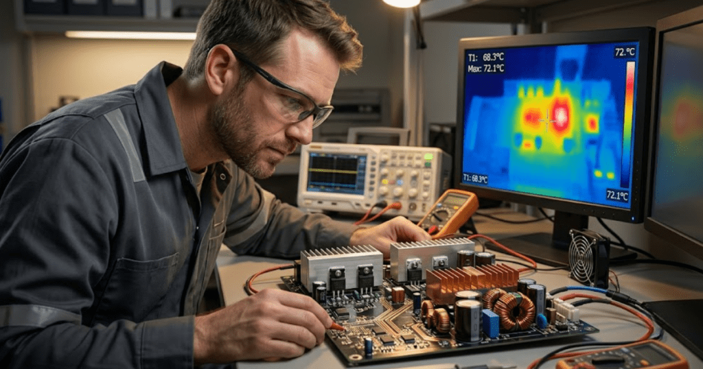
A useful workflow probes the same event at the line entrance, bus junctions, breaker terminals, and apparatus bushings. SPS SOFTWARE fits this task because you can inspect the arrester behaviour and the wave travel in one editable network model instead of treating each device as a black box. That makes it easier to test a close strike, a farther strike, and a switching event without rebuilding the yard for every case. When one node goes over target, you can see if the fix is a new arrester, a shorter lead, or a different placement.
- Measure the line entrance surge and the first clamp level at the same time.
- Check every transformer and reactor terminal against its own withstand target.
- Probe both sides of each breaker during closing and opening duties.
- Review bus tees and branch points where reflections can raise local peaks.
- Inspect cable terminations and open ends for reflected overvoltage
Coverage checks also keep studies honest when a layout changes late in the project. A small shift in conductor length or a new tee connection can move the worst peak to another node. If your study records only one or two voltages, you will miss that shift. A full node check turns lightning protection from a drawing note into a verified electrical result.
Arrester energy duty must be verified for severe cases
Arrester energy duty must be checked because a device that clamps voltage acceptably can still absorb more energy than its thermal design allows. Voltage protection and energy survival are related, yet they are not the same test. Severe lightning and switching cases can pass one and fail the other. You need both results before a case is closed.
A close lightning strike on an incoming line is a clear example. The first current pulse pushes the arrester into conduction, then reflected energy from the yard and the connected line can keep current flowing longer than a simple wave shape suggests. A switching restrike can do something similar with a lower current and a longer duration. Energy duty has to be calculated from the arrester voltage and current over time, not guessed from the peak current alone.
Multiple-event cases deserve attention too. Reclosing after a fault, repeated restrikes, or a sequence of operations during commissioning can stack thermal stress on the same unit. That is why arrester energy duty calculation belongs inside the transient study itself. When you compare the simulated duty against the device capability for the severe cases, you’ll know if the arrester still has margin after it does its protective job.
Simplified assumptions can hide damaging overvoltage peaks
Simplified assumptions hide damaging peaks because they erase the details that create them. Ideal breakers, zero-length leads, single-point voltage checks, and generic arrester curves all push results toward a false sense of security. The missed peak usually appears at a remote terminal. That is exactly where a rules-based placement method leaves a gap.
A substation can look protected when the model uses one arrester at the line entrance, ideal switching, and no branch reflections. The picture changes once you include realistic conductor lengths, a transformer branch, breaker pole spread, and the actual arrester residual curve. A transformer bushing that looked safe at 520 kV can rise well past its coordination margin during a close strike or a restrike event. That shift is not a modelling nuisance. It is the electrical condition your insulation has to survive.
Disciplined transient overvoltage simulation gives you a dependable basis for judgement. You can see where lightning protection coverage holds, where surge arrester placement needs work, and which severe cases set the true design limit. SPS SOFTWARE belongs in that process when you need transparent models that show arrester behaviour and surge travel across the substation, because clear physics leads to clear protection choices. That is how you close protection gaps before a real strike exposes them.