Key Takeaways
-
- Renewable interconnection results are only as sound as the inverter control and protection behaviour represented in the model.
-
- Average models are useful for slow screening tasks, but fault response, weak-grid studies, and compliance checks need higher fidelity.
-
- Transparent modelling workflows help teams update assumptions, answer utility comments, and keep studies aligned with field settings.
Accurate inverter models decide if a renewable integration study will guide a safe grid connection or hide the exact problems the study is supposed to test.
Wind and solar generated 13.4% of global electricity in 2023, so grid studies now hinge on inverter behaviour far more often than on synchronous machine assumptions. You can still complete a power flow with a simplified block, but you won’t get a dependable answer for fault response, ride-through, or feeder voltage control. Utilities, consultants, and plant designers need models that reflect what the controller and protection will actually do. That point matters across every simulation of power system with renewables. A study that misses current limiting, reactive priority, or trip timing will look neat on paper and fail under utility review. Electric power systems with renewables simulations only become useful when the inverter model matches the study question, the grid strength, and the interconnection settings that will be commissioned.
Accurate inverter models set the limits of credible studies
Credible renewable integration studies depend on inverter models that reproduce the plant’s actual control and protection behaviour. Voltage regulation, current limits, phase tracking, and trip logic decide how the plant interacts with the grid. If those functions are simplified away, the study stops matching the equipment that will be installed.
A feeder study on a weak rural circuit shows the problem clearly. A simplified current source can suggest the solar plant will hold active power and stay inside voltage limits during a nearby disturbance. The commissioned inverter will instead hit its current ceiling, shift reactive output, and recover active power on a control ramp. That sequence changes feeder voltage, relay pickup, and the time it takes the plant to return to pre-fault output.
You need model accuracy because utilities don’t approve interconnections from nameplate ratings alone. They assess behaviour under stressed conditions that expose controller limits and protection settings. If the model cannot reproduce those details, the study result becomes a planning guess rather than an engineering basis for connection approval.
“Grid stability studies need explicit inverter limits because those limits decide how much voltage support or active power response the plant can actually supply during a disturbance.”
Average models miss the grid behaviour utilities must assess
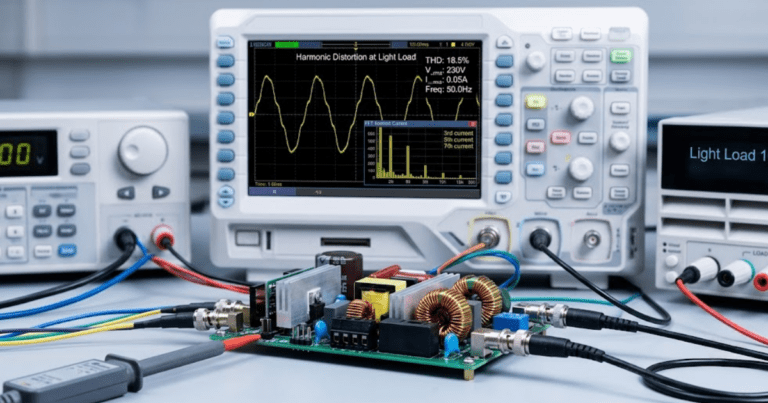
Average inverter models work for slow electrical trends, but they miss the short-duration behaviour that often decides interconnection outcomes. Utilities assess voltage dips, switching events, reclosing sequences, and protection timing. Those events happen on time scales where averaged dynamics hide the response you actually need to see.
A medium solar plant connected near a feeder capacitor bank is a useful example. An average model can show acceptable steady-state voltage before and after a switching event. It often won’t capture the brief overshoot, current saturation, or phase-locked loop stress that follows the step change. Those details matter when a utility wants proof that the plant will stay connected and recover in a controlled way.
This does not mean every study needs detailed switching models. It does mean you should not use an average model for questions about fault ride-through, nuisance tripping, or relay interaction. Average models answer slow questions well, but they leave blind spots exactly where utility review gets strict.
Control loops shape voltage response during solar disturbances
Control loops determine how an inverter reacts when voltage moves away from nominal conditions. The phase tracker, inner current regulator, and outer voltage or power loops each contribute to the response. Their settings decide how quickly reactive current appears, how stable the response remains, and how smoothly active power returns.
A voltage sag on a weak feeder illustrates the point. One controller set can push reactive current quickly enough to help local voltage recover, then restore active power without oscillation. Another set can overshoot, hit current priority limits, and create a second voltage swing as the plant tries to resume export. Both plants can share the same rating and still behave very differently.
You can’t study grid stability with high renewable penetration from nameplate data or generic control blocks alone. The control loops are where plant behaviour becomes system behaviour. When those loops are missing or poorly tuned in the model, you won’t know if a voltage issue came from the feeder, the plant controller, or the way both interacted.
Protection functions decide if interconnection results can be trusted
Protection modelling decides if an interconnection study reflects what the plant will do during abnormal grid conditions. Voltage and frequency thresholds, ride-through timers, reconnect delays, and anti-islanding logic all change the result. A model without those functions can look stable right up to the moment the actual plant trips.
A momentary feeder fault makes this obvious. The network can recover cleanly and the bus voltage can return to normal, yet the plant will still disconnect if the under-voltage timer or frequency window is set more tightly than the study assumed. That single difference changes fault contribution, post-fault loading, and the voltage profile seen by neighbouring customers.
Protection is also where many study disagreements start. Utilities review settings, not just control intent, and small timing differences can flip a result from acceptable to non-compliant. You need the inverter model to include the same thresholds and delays that commissioning staff will apply in the field.
Model fidelity should match the study question first
Model fidelity should be selected from the study objective, the grid condition, and the utility requirement. A simple model is suitable for screening voltage rise or feeder loading under normal conditions. Detailed control and protection models are required when the study must answer how the plant behaves during faults, weak-grid operation, or compliance tests.
You can screen the need for higher fidelity with a short set of checks:
-
- The study asks for fault ride-through or post-fault recovery.
-
- The feeder is weak enough that phase tracking can affect stability.
-
- Protection settings will be reviewed as part of interconnection.
-
- Voltage control functions will operate near current limits.
-
- Compliance depends on specific inverter functions and timers.
Teams often waste time because they start with the model they already have instead of the model the question needs. SPS SOFTWARE fits this stage when you need editable control blocks and transparent parameters that can be matched to a utility study package. That kind of workflow helps you move from screening studies to detailed analysis without rebuilding the entire plant model from scratch.
“Credible renewable integration studies depend on inverter models that reproduce the plant’s actual control and protection behaviour.”
Grid stability studies need inverter limits represented explicitly
Grid stability studies need explicit inverter limits because those limits decide how much voltage support or active power response the plant can actually supply during a disturbance. Current ceilings, reactive priority rules, ramp limits, and phase-tracking constraints define the plant response. If those limits are hidden, the study will overstate system strength.
Planned U.S. utility-scale capacity additions for 2024 included 58% solar and 23% battery storage, which means more study cases will centre on inverter limits rather than on rotating machine inertia. A plant that appears to support voltage during a disturbance can stop helping once its current allocation reaches the controller cap. Another plant can ride through the same event only because its reactive priority is set differently.
The checkpoint below shows where simplified assumptions usually break down.
| Study focus | What the inverter model must represent |
| Steady-state voltage review | A reduced model is acceptable only if voltage control mode and power factor settings match the planned plant configuration. |
| Fault ride-through assessment | The model must include current limiting, reactive current response, and post-fault recovery timing so the plant response is believable. |
| Feeder protection review | Trip thresholds, timers, and reconnect logic must be present because relay coordination depends on exact protection behaviour. |
| Weak-grid stability study | Phase tracking and controller tuning must be modelled because small changes in those loops can create oscillation or loss of synchronism. |
| Voltage regulation study | Reactive power priority and saturation limits must be explicit because the plant cannot supply unlimited voltage support. |
| Commissioning readiness check | The study model must mirror field settings closely enough that test results and study results tell the same story. |
IEEE 1547 checks fail when inverter behaviour is oversimplified
IEEE 1547 compliance studies fail when the inverter model leaves out the exact functions the standard expects a distributed resource to perform. Voltage regulation, frequency response, ride-through, enter-service logic, and protective trip timing all need representation. A generic renewable source block cannot answer those compliance questions on its own.
A utility review for a solar feeder upgrade often asks for proof that the plant will stay connected through specified voltage and frequency excursions while still respecting protective settings. A simplified model can show stable power export and acceptable feeder voltage, yet it cannot prove that the plant’s Volt/VAR curve, frequency-watt response, and reconnect delay match the approved settings. That gap is where compliance studies lose credibility.
You should treat IEEE 1547 checks as behaviour verification. The study has to show how the configured inverter will respond under the same conditions the standard addresses. If the model cannot express those functions, the study won’t support utility interconnection work in a reliable way.
Transparent model workflows support repeatable renewable grid studies

Repeatable renewable grid studies depend on transparent models that engineers can inspect, adjust, and test against utility assumptions. You need to see the control structure, the protection settings, and the imposed limits without hidden logic. That transparency is what turns a simulation result into something your team can defend.
A good workflow keeps the inverter model aligned with the single-line diagram, plant controller settings, and utility study scope from the start. When a review comment asks for a different Volt/VAR curve or reconnect delay, you should be able to edit the model directly and trace the effect through the feeder response. That discipline reduces rework and makes study updates much less fragile.
SPS SOFTWARE belongs in that closing judgment because transparent, physics-based models help you test the exact behaviour a utility will question and an operator will later live with. Accurate inverter modelling will never be a nice extra in renewable integration work. It is the line between a study that informs engineering action and a study that only looks complete.