

Free Trial
Free Trial
Power Electronics|Power Systems
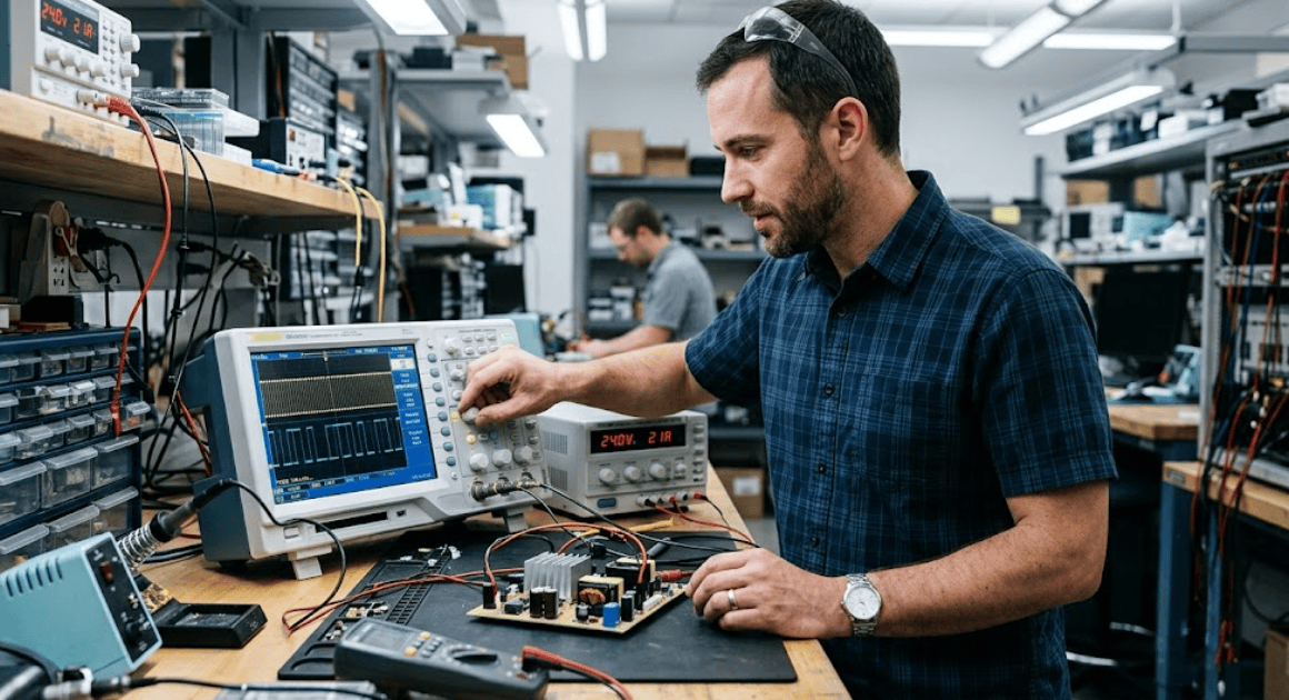
Engineer probing a converter half bridge with an oscilloscope
Power Electronics|Power Systems

5 Gate driver and dead time effects that shape converter behaviour

Key Takeaways

  • Gate driver timing is part of the power stage, so delay mismatch and gate current will shape losses, distortion, and stress before control software responds.
  • Dead time should be set from worst case delay spread, then corrected with compensation for the voltage bias it introduces under load.
  • Timing models that include the full path from driver to device will cut bench iteration and produce safer first hardware settings.

Dead time and gate drive timing will decide how a converter behaves before software control can clean up the waveform.

Motor systems use about 45% of global electricity, so small timing errors inside their converters deserve early design attention. A clean schematic and a stable control loop will not rescue a half bridge that turns on too early or too late. Gate driver strength, propagation delay, and dead time shape voltage error, heat, and device stress long before you start bench tuning. You will get better hardware faster when you treat those settings as part of converter design rather than a final trim step.

Gate driver timing sets converter behaviour before control loops act

Gate driver timing sets the converter’s physical switching sequence, and that sequence fixes what the power stage can do in each cycle. Turn on delay, turn off delay, and gate current define when current commutates. Control software acts later. If the hardware timing is poor, the waveform is already compromised.

A simple half bridge shows this clearly. If the high side device turns off 40 ns later than expected and the low side turns on 20 ns earlier, the overlap is enough to raise cross conduction risk even if your PWM duty cycle is mathematically correct. A motor drive will then show extra heating, noisier current, and a rougher line-to-line voltage than the controller commanded.

  • Dead time shifts average phase voltage.
  • Delay mismatch raises cross conduction risk.
  • Weak gate drive increases switching loss.
  • Extra blanking extends diode conduction.
  • Timing spread breaks one fixed setting.

Those effects are often tuned late because the converter will still run at light load. That bench habit hides the fact that timing is part of the power stage itself. You’re not adjusting polish. You’re setting the physical order and duration of events that determine current path, voltage error, and thermal stress on every switching edge.

Dead time shapes output voltage across each switching interval

“Dead time inserts a small blank interval, but that blank interval changes the average phase voltage every switching period.”

Current keeps flowing while both devices are off, so it commutates through a diode or channel path that was not part of the commanded PWM state. The result is a predictable voltage error.

A low voltage inverter feeding an inductive load makes the effect easy to see. During positive current, dead time after the high side turns off forces current through the low side diode, so the phase node stays lower than the ideal PWM command. Reverse the current direction and the sign of the voltage error flips, even if duty cycle stays the same.

That is why dead time affects a converter most strongly near zero crossings and at low modulation index. The commanded duty cycle can be accurate while the applied voltage is biased every cycle. Current controllers then work harder to correct an error created in hardware, and the correction often appears as distortion, acoustic noise, or uneven torque.

Short dead time raises cross-conduction risk

Short dead time reduces voltage error, but it will raise cross-conduction risk if device turn-off is slower than expected. The unsafe case is not the nominal delay on a datasheet. The unsafe case is the slowest turn-off event across temperature, current, gate resistance, and part variation. That margin must be covered.

Consider a 400 V bridge leg where the upper device has a typical turn-off delay of 60 ns at room temperature. Add a hotter junction, a little more gate resistance from layout, and a slower lot of devices, and that event can stretch far enough that a 50 ns dead time becomes a direct overlap condition. The PWM command did nothing wrong, yet the leg still sees cross conduction current.

Cross conduction and dead time are linked through uncertainty, not just nominal timing. You’re sizing a guard band around the slowest off event and the fastest on event. Lab failures often happen after a load step or thermal soak because those conditions move both delays, and a setting that looked safe at start-up no longer covers the spread.

Long dead time extends body diode conduction

Long dead time extends body diode conduction

Long dead time keeps overlap away, but it also forces current through the diode path for longer than necessary. That raises conduction loss, increases reverse recovery stress in many topologies, and distorts the applied voltage. The penalty grows with current and switching frequency. Safe timing still needs to stay tight.

A traction inverter phase leg under heavy current shows the tradeoff quickly. Add a few hundred nanoseconds of extra blanking and the diode carries current longer on every edge. Junction temperature rises, the phase voltage flattens around transitions, and current ripple can climb even though the control law and bus voltage have not changed.

Long dead time also hides weak gate driver design. Some teams add blanking to stop occasional overlap, but the better fix is often cleaner layout, lower loop inductance, or a gate current profile that turns the device off with more certainty. Extra dead time is useful as insurance, yet too much of it taxes every cycle and every ampere.

Gate drive current sets switching loss during transitions

Gate drive current determines how quickly the device moves through its linear region, and that directly sets switching loss. Faster transitions cut overlap between voltage and current, but they also raise dv/dt and di/dt. Slower transitions reduce electrical stress on some nodes while heating the switch. You’re always trading one limit against another.

A bridge leg that uses a large gate resistor often looks calm on a scope, but the calm edge comes with a longer Miller plateau and more energy burned each turn on and turn off. Another design with a very small resistor switches sharply, then starts to show ringing and false triggering through common source inductance. Gate driver design basics always come back to that balance.

Wide-bandgap semiconductors can reduce power losses by up to 90% in some power conversion stages, which makes timing discipline even more important because transitions are much faster. Dead time selection, gate resistance, and layout can’t be guessed when edge speeds rise. You need settings that match the device physics and the commutation loop.

Dead time targets must cover delay spread

Dead time should cover the full spread of turn-off and turn-on delays, not just a typical number from one operating point. Temperature, bus voltage, current direction, gate resistance, and isolated driver skew all move the timing. A usable target is the smallest blanking interval that still protects the slowest switching case.

A good bench process starts with measured or modelled delay stacks. You add driver propagation delay mismatch, device turn-off spread, and layout-related variation, then keep a modest safety margin. That approach is much more stable than copying 500 ns from an old design that used a different device family and a different current range.

What you check What the timing must include What the chosen dead time protects
Driver propagation delay mismatch between channels The slowest off-channel and the fastest on-channel must both be counted. The setting keeps overlap away when one side responds earlier than the other.
Device turn-off spread across temperature Hot devices and high current cases need more margin than room temperature samples. The setting stays safe after thermal soak instead of only at start-up.
External gate resistance and loop parasitics The effective gate current at the device matters more than the nominal resistor value. The setting covers slower discharge caused by the physical layout.
Current direction at commutation Diode recovery and channel takeover timing will differ with current polarity. The setting avoids overlap in both current quadrants rather than one.
PWM frequency and required waveform quality The blanking must stay small enough that voltage error does not dominate each cycle. The setting protects the devices without adding avoidable distortion and loss.

Dead time compensation restores commanded voltage under load

Dead time compensation corrects the average voltage error created by blanking, so the load sees something closer to the commanded waveform. It does not remove the need for safe timing. It subtracts the predictable bias after you have chosen a dead time that prevents overlap across operating conditions.

A current sign-based compensator is a common starting point. Positive phase current gets one correction polarity, negative current gets the opposite, and the magnitude reflects blanking time and bus voltage. That simple method works well in many motor drives because the voltage error changes sign with current direction and stays roughly proportional to dead time.

Compensation gets more trustworthy when you’ve already modelled the timing chain and current paths carefully. Teams using SPS SOFTWARE can inspect the gate drive sequence, the commutation path, and the resulting phase voltage in one place, then tune the correction against a transparent model rather than guessing from a noisy bench waveform. That makes dead time compensation explained in control code line up with what the switches are actually doing.

“Converters run clean when timing is designed, checked, and compensated before the first prototype forces the lesson.”

Timing simulation should include delays from driver to device

Timing simulation is only useful when it includes the whole path from PWM command to device current commutation. Driver delay, isolation skew, gate resistance, threshold spread, Miller behaviour, and parasitic inductance all matter. A simplified ideal switch model will hide the exact problems dead time is meant to control.

A useful setup starts with one bridge leg and a representative inductive load. You apply the intended PWM, sweep temperature and gate resistance, and inspect gate voltage, drain or collector current, and phase node voltage through each transition. That kind of study will show where overlap appears, where diode conduction lasts too long, and how much compensation your control law should apply.

That is why disciplined timing work belongs near the start of converter design and not at the end of bench debug. SPS SOFTWARE fits that workflow because it lets you inspect transparent switching models and set dead time from physical evidence instead of habit.

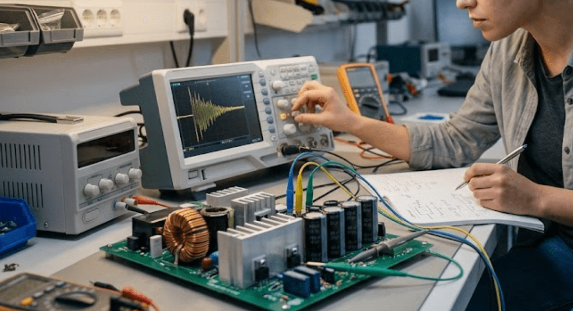
Two engineers inspecting a power converter board under magnifiers
Power Electronics|Power Systems

4 Differences between silicon carbide and silicon MOSFETs in simulation

Key Takeaways

  • Silicon carbide shows its strongest simulation advantage when high voltage and switching loss dominate the converter loss map.
  • Matching gate drive, parasitics, thermal limits, and timing matters more than headline material claims during device comparison.
  • Converter duty cycle ties the main model differences to the final device choice because it sets how often each loss mechanism appears.

Accurate simulation will tell you when a silicon carbide MOSFET earns its place and when a silicon power MOSFET remains the better choice.

Wide bandgap devices can cut power conversion losses by as much as 90% in some applications, which explains why the silicon carbide MOSFET gets so much attention. That headline gain also sets a trap. A simplified model will overstate the benefit, especially when gate resistance, nonlinear capacitance, and junction heating sit outside the study. You need matched conditions before a silicon carbide versus silicon MOSFET result deserves trust.

Silicon carbide fits high-frequency converters with tight loss limits

A silicon carbide MOSFET fits converters where switching loss, bus voltage, and magnetic size set the limit. It performs best in hard-switched or high-frequency stages above a few hundred volts, where silicon devices burn more energy during overlap between voltage and current and during repeated capacitance charging.

An 800 V power factor correction stage running at 100 kHz shows the pattern clearly. Silicon carbide’s critical electric field is roughly 10 times higher than silicon, which allows thinner high-voltage regions and lower resistance in the same voltage class. That material advantage turns into lower simulated loss only when the gate loop and bus inductance reflect the converter you’re actually building.

Frequency alone won’t settle the choice. A 650 V inverter with soft switching can leave less to gain than a 400 V hard-switched boost stage. The useful question is simple: does switching energy dominate your loss map? If it does, a SiC MOSFET will usually repay the extra modelling effort.

Matching test conditions come before any device comparison

Any silicon carbide versus silicon MOSFET study will mislead you unless voltage, current, gate drive, thermal boundary, and parasitics stay matched. Device comparisons fail most often when one model uses default values and the other reflects bench conditions.

“Matching inputs matters more than picking a detailed symbol.”

Lock these five items before you compare parts, or your loss plot won’t mean much.

  • Use the same bus voltage and current waveform for both devices.
  • Set identical gate driver voltage and external gate resistance.
  • Keep loop inductance and stray resistance consistent.
  • Apply the same heat sink and ambient temperature assumptions.
  • Match dead time and the simulation time window.
Checkpoint What stays matched What goes wrong if it drifts
Gate drive conditions Driver voltage, resistance, and source path stay the same for both parts. One switch can look efficient only because it was given an easier turn on or turn off.
Bus parasitics Loop inductance and wiring resistance reflect the same physical layout. Ideal wiring hides overshoot and ringing that fast devices will create on hardware.
Thermal boundary Heat sink, interface resistance, and ambient temperature remain identical. A cooler junction in one model skews conduction loss and safe operating margin.
Load point Bus voltage, current shape, and power level remain fixed during the test. Light-load runs flatter parts that lose ground once current rises.
Dead time Commutation timing stays equal in each leg. Unequal dead time moves diode conduction loss from one device to the other.
Measurement window Both models are averaged over the same settled operating cycles. Short windows can hide heating and capacitance energy that builds over time.

SPS Software helps keep that comparison honest because you can inspect the electrical and thermal assumptions instead of hiding them inside a fixed device block. That matters when a few ohms of gate resistance or a few nanohenries of loop inductance decide the result.

Gate behaviour sets most simulated switching loss results

Gate behaviour decides how fast current rises, how long voltage remains high during turn on and turn off, and how much ringing follows. A silicon carbide MOSFET often looks spectacular in simulation until realistic gate resistance, Miller plateau effects, and source inductance slow the transition.

A 650 V half bridge makes this plain. Set the SiC device with a low gate resistor and an ideal driver, and switching energy falls sharply. Add common source inductance, finite driver current, and separate turn on and turn off resistance, and the advantage narrows to the level you’ll actually see on a board.

The problem isn’t that silicon carbide underperforms. The problem is that gate models are often too kind. Fast edges raise dv/dt, which pushes current through Miller capacitance and can disturb the opposite switch. If you’re modelling a power MOSFET for converter selection, the gate loop is one of the first places to spend effort.

Output capacitance shifts voltage stress during fast edges

Output capacitance shifts voltage stress during fast edges

Output capacitance shapes switching energy, overshoot, and the amount of stored energy that must move during each transition. A silicon carbide MOSFET usually carries lower capacitance at high voltage, but the important detail is its strong nonlinearity. A fixed capacitor value won’t represent that behaviour well enough.

A boost leg at 600 V exposes the issue. Use a constant Coss value from a small-signal table, and the simulated drain voltage slews too smoothly. Use an energy-based or voltage-dependent capacitance model, and you’ll see sharper slope changes, different snubber stress, and a more believable turn off waveform.

That detail matters because capacitance loss repeats every cycle. It also feeds ringing with stray inductance, which affects voltage margin and electromagnetic noise. If your converter uses clamp networks or relies on zero-voltage switching, output capacitance modelling will move the answer more than a tiny change in on-state resistance.

Reverse recovery shapes commutation loss in hard switched legs

Reverse recovery decides how much extra current appears when current transfers from one device path to the other. Silicon carbide parts usually reduce this penalty, while many silicon MOSFETs pay a larger charge extraction cost through the body diode or a companion diode during hard commutation.

A two-level inverter leg gives a clear example. Current freewheels through the lower path during dead time, then the upper switch turns on and must clear stored charge before voltage rises cleanly. If the model omits reverse recovery, the turn-on spike shrinks, the loss estimate falls, and the current stress looks gentler than it will be.

You can’t judge this section from diode charge alone. Dead time, current direction, and junction temperature all shift the result. Hard-switched bridges punish weak commutation behaviour quickly. That is why a silicon device can look fine in a conduction-focused study, then lose ground once you add full transition physics.

Thermal limits decide if efficiency gains survive full load

Thermal limits decide if a simulated efficiency gain survives full load because junction temperature changes resistance, switching energy, and safe operating margin. A cooler device on paper often turns hot once pulse loss, package resistance, and heat sink limits are coupled into the same model.

A 30 kW converter on a shared cold plate shows the risk. At light load, both devices can appear comfortable. Push the model to rated current and include transient thermal impedance, and the hotter switch slows down, loses conduction margin, and can force derating long before the average efficiency number looks alarming.

Steady-state thermal resistance alone won’t protect you here. Cycling duty, startup surges, and uneven leg loading create temperature swings that a single fixed junction value hides. You’re trying to pick a device that stays reliable under stress, so the thermal network must sit inside the switching study, not beside it.

Lower voltage converters still reward strong silicon MOSFET models

Lower-voltage converters often reward strong silicon MOSFET models because conduction loss, package parasitics, and costed gate drive effort outweigh the switching gain of silicon carbide. A SiC MOSFET is not the automatic answer in 48 V, 80 V, or 100 V classes where current is high and voltage is modest.

A 48 V bidirectional converter used for battery buffering is a good test case. The main loss can sit in channel resistance, copper paths, and dead time rather than in high-voltage switching overlap. A modern silicon power MOSFET with low on-resistance and a well-modelled package can outperform a poorly chosen wide bandgap part in total converter loss.

You’re also less likely to need the extreme dv/dt that makes silicon carbide attractive at higher bus voltage. That shifts the design focus toward current sharing, thermal spreading, and package inductance. Good modelling still matters, just for a different reason. You’re checking conduction and thermal balance more than headline switching speed.

Converter duty cycle decides when a SiC MOSFET fits

Duty cycle tells you if a SiC MOSFET deserves the extra modelling burden and device cost. Long high-voltage switching intervals favour silicon carbide. Short low-voltage intervals favour silicon. It turns switching physics into a costed operating pattern you can compare.

“The right power MOSFET choice comes from matched electrical stress, not from material claims or isolated datasheet numbers.”

An 800 V power factor correction stage with frequent hard commutation usually rewards a SiC MOSFET. A 48 V synchronous buck that spends most of its time in conduction usually rewards a strong silicon model instead. Duty cycle links the four decisive simulation differences, because it sets how often gate charge, output capacitance, reverse recovery, and heat actually matter.

SPS SOFTWARE fits this work when you need that judgement to rest on transparent models rather than hopeful assumptions. If you can inspect the gate path, capacitance curves, and thermal network under the same operating point, the silicon carbide choice becomes a measured engineering call instead of a material preference.

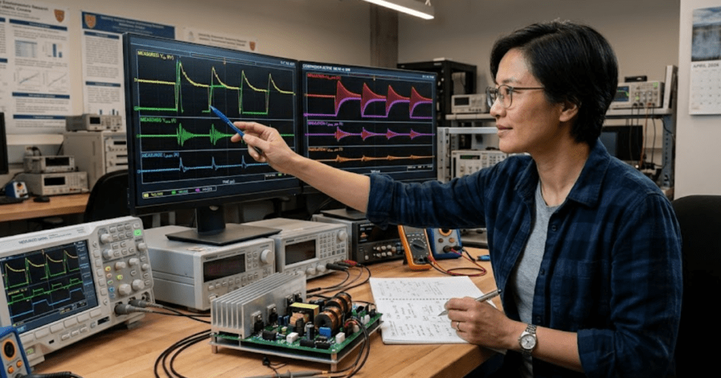
Engineer testing a power converter with an oscilloscope on a lab bench
Power Electronics|Power Systems

Choosing power electronics simulation software for converter design

Key Takeaways

  • The best power electronics simulation software fits the study question and supports the level of detail that question requires.
  • Open device and control models give you results that can be reviewed, adjusted, and defended during design reviews and lab preparation.
  • Speed helps only after model fidelity, workflow fit, and validation checks are aligned with the converter behaviour you need to predict.

Choosing power electronics simulation software for converter design starts with one rule: trust only the models you can inspect and adjust.

More converters now sit inside vehicles, chargers, storage systems, and industrial drives, so small modelling errors carry farther into schedules, test plans, and hardware changes. Global electric car sales passed 17 million in 2024, up more than 25% from 2023. That growth puts more pressure on teams to choose power electronics simulation software that answers the right engineering question instead of producing quick but sealed results.

Converter software choice starts with the study question

The right circuit simulation software depends on the question you need answered. A converter sizing study needs different evidence than a gate timing study. A loss estimate needs different detail than a fault study. Software choice should follow that question first.

A power factor correction stage shows this clearly. If you need input current shape and bulk capacitor size, an averaged model can get you there quickly. If you need switch stress during line transients, the same model will hide the event you care about. A team that skips this distinction usually ends up rerunning work after the first lab mismatch.

You’ll save time when you name the study output before you open the tool. That output might be current ripple, control stability margin, semiconductor loss, or bus overvoltage during a load step. Once that target is explicit, you can judge model detail, solver settings, and result checks with much less guesswork. That is the first filter for any power electronics design tool.

Match model fidelity to the converter behaviour under study

Model fidelity should match the behaviour you need to predict with confidence. Too little detail hides switching effects and parasitics. Too much detail slows routine work without adding useful evidence. Good power electronics design uses the simplest model that still captures the behaviour under test.

A buck converter for control tuning can often start with ideal switches and lumped passive values. The same converter for loss breakdown needs conduction drops, switching energy, dead time, and magnetic resistance. A resonant converter usually needs even more care because waveform shape matters to both efficiency and stress. Fidelity is not a badge of seriousness. It is a fit between the model and the question.

Study focus What the software must represent faithfully
Input and output sizing checks An averaged model is often enough when you only need ripple trends, bus sizing, and steady operating points.
Closed loop tuning The tool should preserve control delays, sampling, and plant dynamics so gain and phase changes appear in the right places.
Switch stress review Switching transitions, parasitics, and commutation paths must be visible or peak voltage and current will be understated.
Efficiency and thermal estimates Device loss mechanisms, magnetic losses, and operating point dependence must be editable or the estimate will look tidy but stay weak.
Protection and fault checks The solver and model set must capture short events, saturation, and controller limits so fault response is not softened away.

Software that supports more than one fidelity level is often the most useful option. You can begin with a fast system model, then move selected sections into switching detail when a question becomes sharper. That staged approach keeps work focused and makes later disagreements easier to trace. It also helps teams compare assumptions instead of arguing over screenshots.

Open device models determine how much results can be trusted

Open device models matter because converter results depend on assumptions that must be visible. If you can’t inspect equations, parasitics, and loss terms, you can’t judge why a waveform looks stable or why a thermal estimate looks low.

“A trustworthy result rests on reviewable model structure and visible assumptions, because polished graphics cannot explain the model.”

A half bridge built with silicon carbide devices makes the point quickly. Output capacitance, reverse recovery, package inductance, and gate resistance all shape overshoot and loss. If those terms sit inside a sealed block, you’re left guessing which default values produced the curve on screen. Editable device models let you test datasheet corners, compare layout assumptions, and document why a parameter changed.

This is where many converter teams lose confidence in their own simulation chain. A result that cannot be audited will stall design reviews, because no one can say which assumption owns the error. Open model power electronics simulation gives you a cleaner path. You can inspect what was modelled, change it deliberately, and explain the impact in plain engineering terms.

Control model access matters as much as circuit fidelity

Control model access matters as much as circuit fidelity

Converter software must expose the control model with the same clarity as the power stage. Sampling, limits, delay, quantization, and protection logic shape current and voltage response just as strongly as device physics. A detailed switching network will still mislead you if the controller sits behind hidden defaults.

A grid tied inverter illustrates the risk. The current loop can look stable in a simplified controller block, then oscillate once saturation, phase delay, and measurement filtering are represented properly. Wind and solar supplied 15.6% of United States electricity generation in 2023, so converter control behaviour now affects far more than a single product bench. Access to the control equations matters because grid interaction, fault ride through, and recovery all sit in that logic.

You should be able to trace a bad transient back to a specific controller assumption. That might be an anti windup clamp, a pulse update delay, or a current sensor filter that was copied from older code. When control models stay open, firmware and power teams can review the same cause chain. That shared visibility turns simulation from a presentation tool into a design tool.

Solver speed matters after accuracy fits the design question

Solver speed is useful only after the model captures the effect you need to see.

“Fast runs support iteration. Fast wrong runs only multiply bad assumptions.”

The best software for converter design gives you enough control over timestep, event handling, and model detail to match speed with purpose.

A resonant converter is a common trap here. Large timesteps can smooth away peak current, soft switching loss, or zero crossing timing that decides device stress. Tightening the solver can expose those events, but it also raises runtime. That tradeoff is acceptable when the question is stress or loss. It is wasteful when you only need a broad operating map.

You’ll get better use from a tool that lets you shift between study modes without rebuilding everything. Start with the plant at a coarse level for operating range checks. Move only the sensitive branch into switching detail when a spike or timing issue appears. Teams often blame the software for slowness when the bigger issue is that they asked one model to answer every question.

Workflow fit depends on integration with control design tools

Workflow fit matters because converter design is rarely a single screen task. You need the circuit model, the controller logic, the parameter set, and the verification notes to stay aligned across revisions. Software that fits your existing control design flow reduces rework and makes reviews far easier.

A digital power supply project shows the difference. The power stage engineer adjusts magnetics and switch timing while the controls engineer tunes current loop gains and fault thresholds. If those edits live in separate files with manual copy steps, mismatches appear quickly. SPS SOFTWARE suits this work when teams need switching level studies with component models they can still open, review, and adapt as assumptions shift.

You should also look at how a tool handles reuse. A good workflow lets you carry a validated leg, filter, or controller into the next design without hiding the equations that made it valid. That matters in industry and in academic labs. Students, researchers, and senior engineers all need the same thing here: a model chain that stays readable after the original author steps away.

Validation methods should reveal assumptions before hardware testing

Validation should expose assumptions early enough to fix them before the first hardware session. Good converter simulation does not end with a plausible waveform. It earns trust through cross checks that tie model behaviour to calculations, datasheets, and measured circuit limits. That is how you separate useful confidence from false comfort.

A practical sequence starts with hand calculations for duty ratio, ripple, and device stress at one operating point. A simplified simulation should match those trends before you add switching details. After that, a detailed model should explain what changed and why, such as diode recovery current or capacitor ESR heating. When the detailed model shifts a result without a clear reason, the issue is usually a hidden assumption or a poor parameter source.

  • The operating point matches a hand calculation at one anchor condition.
  • The control loop still behaves after limits and delays are turned on.
  • The device losses respond sensibly to frequency and current changes.
  • The parasitic values can be traced to layout, package, or datasheet evidence.
  • The model explains any gap between averaged and switching level results.

These checks don’t take long, and they keep lab time focused. You’re not trying to prove a model is perfect. You’re checking that each important assumption is visible, testable, and tied to a physical reason. That discipline is what makes circuit simulation software useful for converters instead of merely convenient.

Common software choices create false confidence in converter results

False confidence usually comes from software choices that hide assumptions behind speed, defaults, or convenience. A clean waveform is easy to trust when deadlines are tight. That trust breaks the moment hardware shows a different switching edge, a slower recovery, or a controller limit you never saw in simulation.

Several patterns show up again and again. Teams pick a tool for its device library, then find that the supplied models cannot be edited enough for a new package or layout. Others run only averaged models, then act surprised when dead time, reverse recovery, or current sampling creates a bench issue. Another group builds detailed switching models but leaves controller delay and saturation at ideal settings, which produces a tidy answer that no firmware build can match.

The safer judgement is simple. Choose power electronics simulation software that lets you inspect the device and control assumptions, match fidelity to the study question, and validate each step before hardware absorbs the cost. SPS SOFTWARE reflects that style of work because switching level modelling and open component models support review, revision, and shared understanding before speed becomes the only thing left to trust.

Power Electronics|Power Systems

7 Best practices for accurate power electronics simulation

Key Takeaways

  • Accurate power electronics simulation depends more on model scope and validation discipline than on adding extra complexity.
  • Device fidelity, parasitics, timing resolution, and steady state setup control most waveform and loss errors in converter studies.
  • Reliable results come from checking the model against power balance and independent reference data before accepting plots as truth.

Accurate power electronics simulation starts with model purpose.

Most converter errors come from poor setup choices, not from missing complexity. If you define the study target first, you’ll pick the right model detail, the right time resolution, and the right checks for waveform accuracy, losses, and stability.

“These seven practices address the setup errors that most often distort converter results.”

Power electronics simulation accuracy starts with model purpose

Power electronics simulation becomes trustworthy when the model answers one clear engineering question. That question sets the needed fidelity. It also sets the acceptable run time. You’re far less likely to tune a model around the wrong waveform when the target is explicit.

A ripple estimate for a buck stage needs different detail than a thermal check for an inverter leg. One study cares about switching edges and passive values. The other cares about loss terms and longer operating windows. Keep these scope markers visible before you touch the solver.

  • Target waveform
  • Operating point
  • Needed accuracy
  • Time window
  • Pass or fail check

These 7 practices improve power electronics simulation accuracy

These seven practices address the setup errors that most often distort converter results. Each one removes a specific source of mismatch between the model and the circuit. Use them in order when you can. That sequence keeps your simulation of power electronics grounded in measurable behaviour.

1. Match device models to the converter operating regime

Device model choice should follow switching speed, voltage stress, thermal range, and the output you need to trust. A simple switch with fixed on resistance works for control tuning in a low-frequency chopper. That same model will miss reverse recovery and output capacitance effects in a hard-switched silicon carbide bridge. You’ll also get the wrong current spike and the wrong loss split during commutation. If your study focuses on average duty response, compact models are enough. If you need turn on loss, diode snap, or dv/dt stress, the device model must include those mechanisms. Model detail should rise only when the study target needs it, or run time will climb without better accuracy.

2. Set parasitic values from measured layout data

Parasitics shape switching waveforms far more than many first-pass models admit. A half bridge with ideal interconnects can look stable and clean, then ring badly on the bench because loop inductance was ignored. A few nanohenries in the commutation path will alter overshoot, current slew, and diode stress. ESR and ESL in the DC link capacitor will also reshape the voltage seen by the devices during edge transitions. You can’t guess these values from textbook schematics and expect good agreement. Pull them from layout estimates, manufacturer data, or measured impedance where possible. Once parasitics are realistic, the simulation stops hiding the resonances that your hardware will actually show.

3. Choose solver steps that resolve every switching event

Time step selection controls whether the solver sees the physics you’re trying to study. A step that skips across turn-on or turn-off intervals will smooth sharp transitions and understate peak stress. A 100 kHz converter with 50 ns edge activity needs much finer resolution than the switching period alone suggests. The same model can look perfectly stable at one step size and clearly unstable at another. Fixed step runs are useful for repeatability, but the step must still capture dead time, diode recovery, and narrow pulses. Variable step runs can help, yet loose tolerances will still bury fast events. If waveforms stop changing when you tighten the step, you’re close to a defendable setting.

4. Start from steady state before capturing waveforms

Waveforms are only meaningful when the converter has settled into the operating point you want to examine. Starting a loss study from zero current and zero capacitor voltage will contaminate the first cycles with startup behaviour. That makes current ripple, switch stress, and average power look worse or better than they really are. A boost converter near 70% duty can need many cycles before the inductor current and output voltage stop drifting. It’s worth running an initial settling window, then collecting data after the transient dies out. You’ll save time during analysis because the measured interval actually represents the target mode. It’s also easier to compare against bench captures taken after the hardware has stabilised.

5. Model gate drive timing with realistic dead time

Gate signals are part of the power stage model because timing errors directly alter conduction paths. Ideal complementary pulses with zero delay can hide shoot-through risk or erase body diode conduction that will appear in hardware. A synchronous buck stage shows this clearly when a few tens of nanoseconds of dead time shift current from the channel into the diode. That shift affects efficiency, reverse recovery, and device temperature. Don’t stop at nominal dead time either. Add propagation delay mismatch, rise and fall differences, and gate resistance effects when those terms matter to the study. If your timing model is too clean, the electrical results will be too clean as well.

6. Check losses with energy balance across each cycle

Loss estimates become more believable when they agree with a simple energy balance. The average input power should line up with output power plus stored energy change plus losses over the sampled interval. If those terms don’t reconcile, the issue is often a sign error, an averaging window that is too short, or missing conduction and switching terms. A phase-shifted full bridge can show plausible switch loss values while total power still fails to balance because magnetics or snubber losses were omitted. Use cycle-based checks before trusting thermal results. It’s a fast way to catch hidden mistakes. Once the power balance closes, every later temperature or efficiency calculation rests on firmer ground.

“Once the power balance closes, every later temperature or efficiency calculation rests on firmer ground.”

7. Validate waveforms against independent reference results

Validation means comparing the model against something outside the model itself. Bench measurements are strongest, but analytical checks, manufacturer curves, and peer-reviewed reference cases also help. A diode current waveform that matches your expectation in shape but misses the reverse recovery peak still fails validation. The same goes for efficiency results that look smooth yet miss measured conduction loss at light load. Open model inspection matters here because you need to trace what each equation is doing. SPS SOFTWARE fits this step well because the component models are transparent enough for you to inspect parameters, equations, and assumptions instead of treating the block as a sealed box.

What to focus onWhat the practice protects
1. Match device models to the converter operating regimeThe chosen device model must include only the switching effects that matter to the study target.
2. Set parasitic values from measured layout dataMeasured or estimated interconnect and passive parasitics keep ringing and overshoot from being hidden.
3. Choose solver steps that resolve every switching eventTime resolution must be fine enough to capture narrow pulses and commutation details.
4. Start from steady state before capturing waveformsOnly settled operating intervals should feed ripple, stress, efficiency, and loss checks.
5. Model gate drive timing with realistic dead timeTiming details decide which device conducts and how much switching stress appears.
6. Check losses with energy balance across each cyclePower balance reveals missing terms and bad averaging before thermal results are trusted.
7. Validate waveforms against independent reference resultsIndependent checks stop a tidy model from passing when its physics still disagree with measured behaviour.

How to apply these practices to converter studies

Start each converter study with one operating point, one pass or fail metric, and one validation target. That simple structure keeps the model scoped correctly. It also tells you what detail to keep. You’ll get useful results faster because each setup choice serves a defined purpose.

A classroom buck converter, a lab scale inverter, and a research prototype will all use the same discipline even when their complexity differs. Set the study goal, add only the physics that influence that goal, then verify solver settings, timing, parasitics, and power balance before you trust the plots. SPS SOFTWARE supports this kind of work well because transparent models make each assumption easier to inspect, question, and refine.

Power Electronics|Power Systems

Thermal modeling for power electronics and why switching losses matter

Key Takeaways

  • Switching losses come from voltage and current overlap during finite transitions, and high frequency turns small event energies into significant heat.
  • Datasheet energies, thermal impedance, and junction temperature feedback belong in the same model if you want reliable converter thermal results.
  • Gate resistance, layout parasitics, and transient thermal swings often set the safe operating limit before heatsink size does.

Switching losses decide junction temperature sooner than most heatsink calculations admit.

A field failure survey summarized in the IEEE reliability literature found that power semiconductor devices accounted for 31% of reported failures in power electronic systems. That matters because thermal stress is rarely created by conduction loss alone in modern converters. Once your switching frequency climbs, each turn on and turn off event adds a small burst of energy that turns straight into heat. If you only size copper, silicon area, and heatsinks around average current, you’ll miss the part of the loss budget that often sets the safe operating limit.

“That overlap creates energy loss in every cycle.”

Switching losses decide junction temperature sooner than most heatsink calculations admit.

A field failure survey summarized in the IEEE reliability literature found that power semiconductor devices accounted for 31% of reported failures in power electronic systems. That matters because thermal stress is rarely created by conduction loss alone in modern converters. Once your switching frequency climbs, each turn on and turn off event adds a small burst of energy that turns straight into heat. If you only size copper, silicon area, and heatsinks around average current, you’ll miss the part of the loss budget that often sets the safe operating limit.

Switching loss starts during finite voltage current overlap

Switching loss begins when drain to source voltage and drain current exist at the same time during turn on and turn off. A MOSFET is not an ideal switch that jumps from fully blocking to fully conducting. Gate charge, parasitic capacitances, and circuit inductance stretch the transition. That overlap creates energy loss in every cycle.

A hard switched half bridge makes this easy to picture. During turn on, the current rises while the device still supports much of the bus voltage. During turn off, the current is still flowing while voltage climbs again. The product of voltage and current during those short intervals creates switching losses in MOSFET devices, even if the on state resistance is low and the conduction interval looks efficient.

You can’t treat those intervals as rounding errors once frequency rises. A converter running at 20 kHz may tolerate a rough estimate early in design, but a design at 100 kHz or 250 kHz will turn a few microjoules per edge into watts of heat. That’s why accurate thermal modelling starts with the overlap event, not with the heatsink.

A simple switching loss formula works only for screening

The common screening formula estimates switching power from the overlap triangle during turn on and turn off. You multiply bus voltage, load current, and transition time, then scale that event energy with switching frequency. It gives a quick first pass. It will not capture the full behaviour of an actual converter.

You’ll often see the estimate written as Psw ≈ 0.5 × V × I × (tr + tf) × fs. That form is useful when you’re comparing candidate devices for the same bus voltage and current. A 400 V converter switching 20 A with combined rise and fall time of 80 ns at 100 kHz produces a rough estimate near 32 W. That number is helpful for screening, but it hides reverse recovery, output capacitance loss, gate loop effects, and load current variation.

The formula also assumes linear transitions and constant current. Actual waveforms rarely behave that cleanly. Parasitic inductance can slow one edge and sharpen the other. A clamped inductive load will produce a different switching shape than a resonant leg. Use the simple formula to reject weak options early, then move to measured or simulated energy per event before you trust a thermal result.

Datasheet curves account for voltage current temperature dependence

Datasheet switching energy curves are more useful than the simple overlap formula because they include how the device behaves under tested voltage, current, gate resistance, and temperature conditions. Those curves convert switching losses in MOSFET parts from guesswork into a parameterized estimate. They still need correction for your exact circuit.

A typical datasheet gives turn on energy and turn off energy at a stated bus voltage, current, and gate resistance. If your converter runs at half the tested current, you can’t assume the energy will scale perfectly in half. The output capacitance discharge, reverse recovery of the companion diode, and Miller plateau behaviour distort that scaling. Junction temperature also matters because carrier mobility, threshold shift, and parasitic behaviour all change with heat.

When you read those plots, treat test conditions as part of the number. A curve measured at 25°C with a 10 Ω gate resistor will understate loss for a converter that actually runs near 100°C with a 22 Ω resistor. This is where you stop thinking about one MOSFET value and start thinking about a switching system.

Average power follows event energy times switching frequency

Average switching power comes from the sum of turn-on and turn-off energy per event multiplied by switching frequency. That relationship is the most reliable bridge between waveform detail and thermal design. Once you know event energy under your conditions, the thermal model has a meaningful heat source to solve.

The practical form is Psw = (Eon + Eoff) × fs. If one device dissipates 120 µJ at turn-on and 90 µJ at turn-off, a 100 kHz operating point gives 21 W of switching power. Double the frequency and that term doubles too, even when load current and duty ratio stay the same. That linear link is why high-frequency designs often become thermal problems before they become current problems.

The checkpoint below helps separate the inputs that deserve attention first when you calculate MOSFET switching losses for simulation and thermal sizing.

Input or checkWhat it tells you
Bus voltage under worst operating conditionThe highest applied voltage will stretch the switching energy and usually sets the harder thermal case.
Load current at the instant of switchingThe current during each edge matters more than average output current when you estimate event energy.
Turn on and turn off energy from matched test conditionsUsing energies measured near your gate resistance and temperature avoids a large error in average power.
Switching frequency across the operating rangeA modest increase in frequency raises switching power in direct proportion and often moves the thermal limit first.
Conduction loss calculated at hot resistanceHot on state resistance keeps the total loss budget honest once switching heat has already raised junction temperature.
Dead time and diode recovery behaviourThese details often explain why measured loss is higher than a clean energy sum from a datasheet curve.

Electrothermal simulation links switching events to junction temperature

Electrothermal simulation turns electrical loss into junction temperature by coupling a loss model with a thermal network. That link matters because device temperature shifts the same parameters that created the loss. You’re solving a loop, not a one way calculation. A static estimate will miss that feedback.

A useful converter model starts with electrical waveforms or event energies, then feeds those losses into a thermal impedance path from junction to case, case to sink, and sink to ambient. The updated junction temperature then adjusts on state resistance, threshold behaviour, and switching energy for the next step. That is how you move from a spreadsheet number to a believable operating point. SPS SOFTWARE fits this workflow when you need transparent electrothermal blocks that you can inspect and adjust instead of accepting a hidden thermal assumption.

The value of this approach shows up when operating points shift. A converter that looks safe at nominal load may cross a thermal limit during light load high-frequency operation, where conduction loss falls but switching loss still stays high. Once you model that loop, you’ll see why thermal effects belong inside converter simulation rather than after it.

“You’re not only tracking the average hot spot. You’re tracking how far and how often the junction moves.”

Transient impedance shapes temperature rise more than steady averages

Transient thermal impedance tells you how quickly a device heats during pulsed loss, and that matters more than steady thermal resistance when switching power is uneven over time. Junction temperature follows pulses, bursts, and duty cycles with delay. Average dissipation alone will hide those peaks. Short overloads can still push silicon past a safe temperature.

A motor drive shows this clearly during acceleration. Current rises for a few hundred milliseconds, switching energy increases, and the junction responds much faster than the heatsink. The case may still look cool while the die has already reached a dangerous peak. A commonly used power cycling data set showed lifetime dropping from about 10 million cycles at a 60 K junction swing to about 1 million cycles at 100 K, which shows why transient temperature swing matters so much.

That is why thermal modelling improves power converter reliability. You’re not only tracking the average hot spot. You’re tracking how far and how often the junction moves. Packaging fatigue, solder stress, and bond wire wear respond to those swings, so transient impedance belongs in the model from the start.

Gate resistance tuning sets the first switching loss tradeoff

Gate resistance is often the first knob you turn because it directly alters switching speed, voltage overshoot, ringing, and electromagnetic noise. Lower resistance reduces overlap time and cuts switching loss. Higher resistance softens edges and can protect against overshoot. You won’t get the best result from either extreme.

A synchronous buck converter with a very small gate resistor will switch quickly and run cooler in the silicon, yet the drain waveform can overshoot enough to stress the device and raise noise. A much larger resistor will calm the edge, but transition time will lengthen and switching power will climb. The right value depends on package inductance, gate driver strength, and layout quality as much as the MOSFET itself.

  • Use a smaller gate resistor when overlap loss is the main thermal limit.
  • Use a larger gate resistor when overshoot or ringing threatens device margin.
  • Check turn on and turn off separately because the best values often differ.
  • Measure at hot conditions because edge speed shifts with junction temperature.
  • Retune after layout changes because parasitic inductance changes the result.

That tradeoff is why reducing switching losses in MOSFET-based converters is rarely a single part choice. Gate drive settings, loop inductance, and thermal margin all move as a group. You’ll get a better answer from measured waveforms and a coupled model than from a nominal resistor value copied from a reference design.

Heatsink sizing fails when switching loss is undercounted

A heatsink calculation fails when the loss number feeding it ignores switching energy, temperature feedback, or transient peaks. The sink can be perfectly sized for the wrong power input and still produce an overheated converter. Good thermal design starts with disciplined loss modelling, then uses the heatsink as the last step rather than the first guess.

A common failure path looks harmless on paper. You choose a low resistance device, estimate conduction loss at room temperature, and pick a sink that seems to hold the case comfortably below its limit. Bench tests then show the junction climbing during high-frequency operation because switching losses in MOSFET devices were understated. That missing heat raises junction temperature, which raises on-state resistance, which pushes total loss higher again. The error compounds rather than staying fixed.

SPS SOFTWARE is most useful at this stage when you want the electrical and thermal assumptions kept visible enough to challenge. That habit will give you better converter margins than any oversized heatsink alone. Careful modelling won’t remove tradeoffs, but it will show you which ones are worth paying for and which ones are just hidden loss.

Cart Overview