

Key Takeaways
- Subsynchronous resonance is a damping problem that only becomes clear when electrical, mechanical, and control loops are studied as one system.
- Series compensation and converter controls can both supply energy to a subsynchronous mode, so the source of oscillation must be identified before mitigation is selected.
- Time domain models with the right control, network, and shaft detail give you evidence you can act on, while steady state studies only tell you where to look next.
Subsynchronous resonance in converter-heavy grids can only be trusted when you study it in detailed time-domain simulation.
Grid composition now includes far more power electronic sources than older screening methods assumed. Renewable capacity additions reached almost 510 GW in 2023, with solar photovoltaic accounting for about 75% of that growth. That shift matters because controls, network resonance, and shaft mechanics can now meet in the same study space. If you rely on steady-state snapshots, you won’t see the feedback loop that turns a mild disturbance into repeated current and torque stress.
Subsynchronous resonance begins with energy exchange below synchronous frequency
Subsynchronous resonance is sustained energy exchange below the grid fundamental, usually between the network and a mechanical shaft or converter control loop. The signal sits under 50 or 60 Hz. Risk appears when damping is low enough for each cycle to feed the next one, so you’re looking for growth rather than a low-frequency component alone.
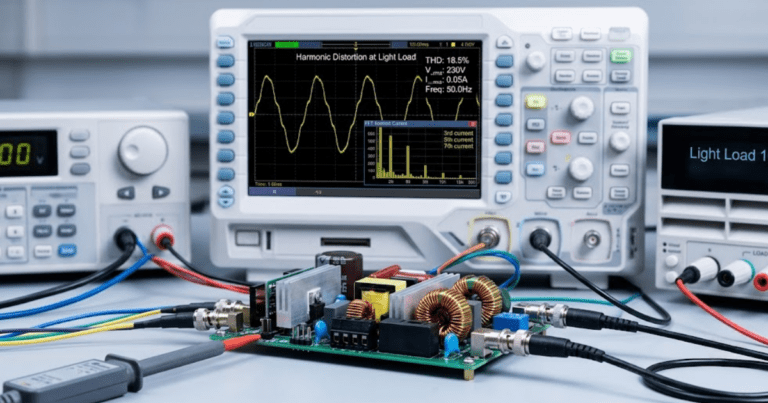
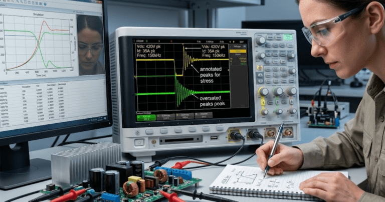
A practical case helps fix the idea. A 60 Hz system can show an electrical oscillation near 25 Hz after a fault clears on a series compensated line. Current at that frequency can pass through a generator shaft or a wind plant controller and return with more energy than it lost. Oscillography will then show a rising envelope on current, electrical torque, or shaft torque even after the initiating event has ended.
That distinction matters because many studies stop after spotting a resonance frequency. Frequency alone does not confirm a harmful mode. A stable 25 Hz component that decays quickly is a different problem from a 25 Hz mode that grows for several seconds.
“Good studies treat subsynchronous resonance as a closed loop question, with source, path, phase, and damping all represented.”
Series compensation can couple electrical resonance with shaft torque
Series compensation shifts the line’s electrical natural frequency downward, and that can place it close to a torsional mode of a turbine generator shaft. Once those frequencies line up, the network can exchange energy with the shaft every cycle. Torque reversals then rise faster than current plots alone suggest. Torsional interaction becomes visible only when electrical and mechanical states are solved at the same time.
Consider a long transmission corridor with 40% series compensation on a 60 Hz system. The capacitor and line inductance can place electrical resonance near 30 Hz. A nearby steam unit might have a shaft mode around 28 to 32 Hz across turbine sections. A fault, line switch, or power transfer step can then excite both sides at once, and the shaft sees alternating torque that repeats long after voltage appears to recover.
You can miss this with a simplified generator model. A single lumped inertia shows rotor speed movement, yet it won’t reveal which shaft section takes the stress. Utilities learned this in classic SSR events, and the lesson still stands in converter-heavy grids. Series capacitors are not the problem on their own. Trouble starts when compensation, operating point, and a lightly damped mode occupy the same frequency band.
Converter controls can create subsynchronous oscillation in wind plants
Wind plants can produce subsynchronous oscillation when converter controls interact with weak grids, series compensation, or neighbouring control systems. The mechanism sits in software and power electronics rather than a turbine shaft alone. Phase locked loops, current regulators, outer power loops, and dc link controls can all add or remove damping. This is often called subsynchronous control interaction when the controller is the main energy source.
Texas had 42,640 MW of installed wind capacity at the end of 2023. That scale explains why a wind plant connected through a series compensated corridor deserves more than a basic load flow check. One common case uses a doubly fed induction generator plant whose rotor side converter reacts strongly near the network resonance. Another case appears in a full converter plant when a tight phase locked loop meets a weak point of interconnection.
The visible symptom is often current or power oscillation rather than obvious mechanical distress. Plant-level controls can also mask the source because turbines share a collector system and plant controller. If you only check one inverter against an ideal bus, you’ll miss collector impedance, cable capacitance, and controller interactions across units. Converter-heavy grids need plant level modelling before you can trust the damping sign.
Steady state studies miss the feedback loops that matter
Steady state studies miss subsynchronous problems because they solve operating points, not dynamic energy exchange. Load flow, short circuit duty, and basic voltage screening are still useful, yet they can’t show a growing 20 to 40 Hz mode. Control states, limiter action, and phase delay sit outside their scope. You can’t infer damping from a snapshot.
A common failure appears after a voltage dip. The post-fault operating point looks acceptable, line loading is within limits, and capacitor duty seems normal. The converter, though, may pass through a current limit, shift control priority, and return with a different effective impedance at subsynchronous frequency. That sequence decides stability, and it exists only in time.
Protection adds another blind spot. A crowbar, bypass gap, protective relay, or capacitor protection logic can change the network structure during the event you’re studying. Those actions alter frequency, damping, and current path at the exact moment the mode is forming. Screening studies are good for narrowing where to look. They can’t settle if the oscillation will decay, persist, or grow.
Time domain simulation must represent the full feedback loop
Time domain simulation captures subsynchronous resonance only when the full loop is represented from disturbance to response and back again. That means network impedance, controls, protection, and any relevant shaft dynamics must interact at the simulation time step. Event timing matters because milliseconds can alter phase. A model that omits one active part of the loop can give the right frequency and the wrong damping.
A useful study sequence starts with a credible operating point, then applies a specific event such as fault clearing, line energization, or a power reference step. You then track current, electrical torque, shaft torque, control outputs, and bus voltage for several seconds after the event. SPS SOFTWARE fits this workflow when you need transparent models that can be inspected and adjusted instead of treated as sealed blocks. That visibility matters when you’re trying to explain why a mode grows.
| Model feature to include | What goes wrong if it is omitted | Why the omission matters |
| The series capacitor and its protection states must be modelled. | The resonant frequency can shift away from the value seen on the actual line. | You will assess the wrong frequency band and miss the event that starts the oscillation. |
| The shaft must be split into relevant masses when torsional risk exists. | A single inertia can hide the section that sees the largest alternating torque. | Mechanical stress can be severe even when rotor speed looks modest. |
| Inner converter loops need their actual gains and filters. | Average behaviour can look damped even when the implemented controller adds energy. | The sign of damping can reverse with small control changes. |
| Protection and limiter logic must switch during the event. | The study will keep the system in a state that never exists in service. | Mode growth often starts during temporary logic states rather than steady operation. |
| Several operating points should be tested across power transfer and grid strength. | A stable base case can hide an unstable condition near a dispatch limit. | Subsynchronous risk depends strongly on where the plant is operating. |
Good execution does not mean excessive detail everywhere. It means the detail matches the active physics of the loop you are testing. If the question is shaft torque, you need shaft detail. If the question is converter control interaction, controller timing and network frequency response deserve priority. That discipline turns simulation into evidence instead of animation.
Model detail determines if subsynchronous control interaction appears
Subsynchronous control interaction appears only if the model preserves the control dynamics that shape subsynchronous impedance. Average blocks with ideal measurements can erase the delay, filtering, and limiter behaviour that create the instability. The same is true for overly simple network equivalents. Model detail is not about making everything large. It is about keeping the details that set phase and damping at the frequencies of concern.
A grid equivalent behind the point of interconnection can be useful for screening, yet it becomes risky when it hides resonant poles from adjacent lines or collector feeders. A phase locked loop model without its measurement filter can look calmer than the implemented controller. A one mass turbine model can also suppress torsional splitting that matters when electrical resonance sits between shaft modes. Each simplification removes a possible feedback path.
You don’t need transistor-level switching for every study, and you don’t need to model every wind turbine in full detail. You do need the implemented control structure, realistic delays, collector system impedance, and enough mechanical resolution to expose the stress path. If your results swing from stable to unstable after small parameter corrections, that doesn’t mean the simulation failed. It means the system is sensitive and your margin is thin.
Detection depends on mode growth across current, speed and torque
Detecting subsynchronous resonance means checking how a mode grows across electrical and mechanical signals after a credible disturbance. No single trace is enough. Current can look modest while shaft torque rises sharply, and plant power can oscillate while individual controls saturate. You’ll get a trustworthy answer only when signals are reviewed as one coupled response.
- Track line current spectra below the fundamental after each disturbance.
- Measure shaft torque or equivalent mechanical stress where rotating machines are present.
- Record converter internal states such as phase angle, current references, and limiter status.
- Compare damping at several operating points instead of one dispatch level.
- Check if the oscillation survives after the initiating event is fully cleared.
A useful diagnostic pattern is rising subsynchronous current, a lagged change in control output, and a matching increase in torque ripple or power oscillation. Another pattern shows stable current at one dispatch point and unstable growth at a higher transfer level, which tells you operating range matters as much as topology. You’ll also want to separate forced response from natural mode growth. A forced oscillation follows an external source, while subsynchronous resonance keeps feeding itself after the trigger ends.
“You can’t manage this class of risk with static studies and broad assumptions, because the damaging mechanism sits in timing, coupling, and damping.”
Mitigation must target the loop that sustains oscillation
Mitigation works when it targets the specific loop that supplies energy to the subsynchronous mode. That could mean shifting the electrical resonance, adding damping in a controller, blocking an operating range, or changing protection timing. Generic fixes waste time because the visible symptom is often far from the actual source. A torque problem can start in a converter loop, and a current problem can start in network compensation.
A line study might show that reducing series compensation moves the electrical resonance away from a shaft mode and ends torsional stress. A wind plant study can show that retuning a phase-locked loop or current controller adds enough damping to stop a 25 Hz oscillation without changing dispatch. Another case can require a supplemental damping function because the plant must keep its compensation level and operating range. Each fix follows from the loop identified in simulation, not from a standard checklist.
Disciplined modelling is what turns subsynchronous resonance from a surprise into a tractable engineering problem. SPS SOFTWARE belongs in that process when you need editable time domain models that show how the loop behaves before equipment absorbs the lesson. That judgment holds across utility studies, research work, and teaching labs because the physics do not simplify themselves for convenience.