Key Takeaways
-
-
Simulation should act as a gate before lab work, not as a loose design aid.
-
Corner cases, control margin, thermal stress, and fault response will expose most prototype rework before hardware exists.
-
A short pass checklist gives design, test, and management teams a shared threshold for first power up.
-
Testing a power converter before hardware build will cut the most expensive prototype mistakes.
Control loops fail in the lab because assumptions looked clean on paper, not because the board was unlucky. Thermal stress shows up after minutes of operation because device loss and cooling paths were only estimated. Protection settings trip late because fault current paths were never exercised. A disciplined simulation gate fixes those problems while the design is still cheap to edit.
Failure data points to the same pattern. A widely cited breakdown of power electronic system failures puts capacitors at about 30% of failures, which means electrical and thermal stress checks deserve attention long before first power up. The best power converter testing workflow starts with a model you can challenge, then moves through nominal operation, corners, control, heat, and faults before a board earns lab time. You won’t reduce converter prototype iterations with bench fixes alone.
Validation starts with a simulation gate before hardware
“A sound validation flow starts with a simulation gate that every converter must pass before layout release or bench power up.”
That gate will check steady state behaviour, startup, shutdown, control response, and basic fault handling. You’re not looking for perfect correlation yet. You’re proving that the design behaves sensibly under the cases you already know will matter.
A 48 V to 12 V synchronous buck is a simple example. If startup overshoot exceeds the output capacitor rating in simulation, the board will not become safer after fabrication. If the current limit chatters during a load step, that is already a bring up problem waiting to happen. Those issues cost minutes to correct in a model and days to correct after assembly.
This gate also sets team discipline. Layout, firmware, and test staff will work from the same expectations once the simulated waveforms and acceptance limits are written down. That shared checkpoint is the best way to validate a power converter prototype before lab testing because it forces design intent into results you can review, challenge, and repeat.
Model fidelity determines how much simulation results can prove
Model fidelity sets the limit on what your simulation can actually prove. Ideal switches, lossless magnetics, and perfect sensors will hide the very behaviour that breaks prototypes. You need a model that includes parasitics, delays, offsets, and temperature-dependent loss. That level of detail will turn simulation from a sketch into a validation tool.
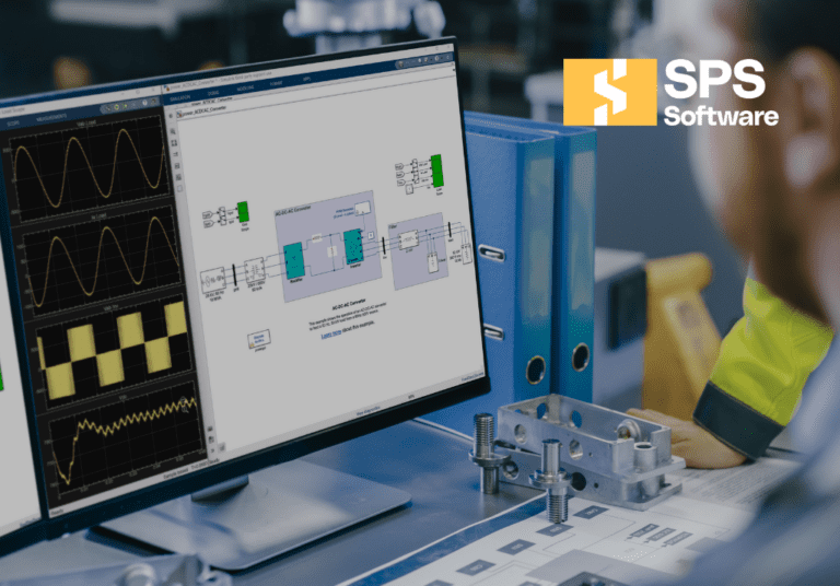
A converter can look stable with zero gate delay and no trace inductance, then ring hard once the real loop is built. The same design can appear cool if switch loss uses a single fixed number instead of current and temperature-dependent curves. SPS SOFTWARE fits this stage because the model remains transparent enough for you to inspect equations, edit assumptions, and trace where a result comes from while you’re testing assumptions.
Fidelity does not mean modelling everything. It means modelling the pieces that move the answer. Current sense filtering, dead time, inductor DCR, output capacitor ESR, and heat flow into the board will often matter more than package cosmetics or a perfect three-dimensional geometry. When your model can explain expected failure modes, you can trust its passes and treat its warnings seriously.
Topology choices need proof at nominal operating points
Nominal operating points are where topology choices earn their place. A converter must first meet target voltage, current, ripple, and efficiency at rated conditions before you spend time defending it at the edges. This is the cleanest checkpoint for power converter design validation. If the basic conversion job is weak, no corner case work will rescue it.
Consider a design team comparing an isolated full bridge with an active clamp forward stage for the same output power. Rated input and rated load will show switch stress, transformer utilization, and current ripple without corner case noise. One option will often show cleaner device margins, simpler control, or a better thermal split. That early proof narrows the design before layout details bury the main issue.
The same check keeps nominal passes honest. You want output regulation, expected duty cycle, believable efficiency, and sensible loss distribution at one stable point before moving on. A design that only meets the target after hand tuning compensation, ideal gate drive timing, or optimistic magnetics data has already told you it will consume prototype iterations. It won’t become robust once copper is fixed.
Operating corners expose limits before the first build

Operating corners show where a converter stops being robust and starts relying on luck. You will only see those limits when you sweep line, load, temperature, and component tolerance beyond the comfortable midpoint. Corner testing in simulation is cheaper than discovering the weak case under a camera, a heat sink, and a deadline. It also gives you a ranked list of what needs redesign first.
A common failure case appears at low input voltage and full load, where duty cycle rises, current climbs, and control margin shrinks at the same time. Another shows up at high line and light load, where minimum on time, burst behaviour, or output overshoot become the issue. Cold start into a prebiased output can expose reverse current and diode stress that never appeared at nominal conditions.
|
Operating condition |
What the result must show |
|---|---|
|
Low input voltage at full load |
The converter must regulate output without exceeding current limit or pushing magnetic parts into saturation. |
|
High input voltage at light load |
The control law must avoid pulse skipping problems, excess overshoot, and unsafe switch voltage stress. |
|
Maximum ambient temperature |
Loss distribution must stay within part ratings once conduction and switching loss rise with heat. |
|
Cold start with a pre-biased output |
Startup must avoid reverse current spikes and false protection trips that can upset the load. |
|
Component tolerance limits |
The design must keep regulation and stability margin when capacitance, resistance, and gain shift from nominal values. |
That table works as a pre-hardware converter checklist because it ties each corner to a clear pass condition. Once you know which corner breaks first, redesign becomes focused. You stop guessing and start fixing the limit that actually matters.
Control stability needs margin across expected disturbances
Control validation means proving stable response across the disturbances your converter will actually face. A single clean transient at room temperature is not enough. You need margin across line steps, load steps, startup, shutdown, and sensing noise. Stable control has to hold across a range of cases.
A current mode converter that looks tidy at nominal load can become erratic when output capacitance falls with bias and temperature. Load release can drive overshoot high enough to trip downstream electronics even though small signal plots still look acceptable. Another weak case shows up when current sense filtering adds just enough delay to spoil a fast compensation design.
You are looking for behaviour that remains controlled when the model is stressed. That includes settling time, overshoot, current limit entry, integrator recovery, and duty cycle clamp interaction. If the compensation only works after repeated tuning at one point, you can’t call the design robust. That is why control work belongs before bench time, when it is still easy to adjust plant assumptions and controller structure without touching copper.
Thermal stress must be checked before first power-up
Thermal validation must happen before first power up because temperature will reshape electrical behaviour and part life. Junction rise, copper heating, magnetic loss, and air path assumptions must all be checked together. A cool schematic can still become a hot board. Heat still deserves a full design check before converter testing starts.
A compact non-isolated converter often concentrates loss in the high-side switch, output inductor, and freewheel path. If those parts sit close to each other, the local temperature rise will stack rather than spread. The same failure breakdown that assigns capacitors about 30% of failures also assigns semiconductors about 31%, which is why junction temperature deserves device-level attention.
That is why thermal checks need more than a total loss number. You want device-level loss, thermal resistance assumptions, airflow limits, and heat spreading through the board or sink.
“A prototype that passes electrical tests for ten seconds can still be a poor design if one hotspot will age the output capacitor, shift current sharing, or push current sense drift beyond your control margin.”
Fault cases should be simulated before protection settings freeze
Fault simulation should happen before protection settings freeze because protection belongs inside converter behaviour and must be designed as part of the circuit. You need to know what the circuit does during short circuits, overloads, startup faults, sensor loss, and switch failures. A converter is only validated when it fails in a controlled way. Good protection limits damage and gives clear recovery behaviour.
A bench short on the output is not the only fault that matters. Startup into a latched downstream load can look like a persistent overload. Loss of current feedback can force duty cycle high enough to over-stress the power stage before a slower voltage loop reacts. One shorted switch model will also reveal if your gate logic and dead time assumptions still protect the opposite device.
The key question is sequence. Which comparator trips first, what gets disabled, how much energy moves before current falls, and what state does the controller enter next? Those answers will shape sense resistor sizing, blanking time, latch logic, and restart method. Simulating converter faults before lab testing will keep you from setting protection thresholds on hope and scope reflexes.
A pre-hardware checklist sets the lab entry threshold
A pre-hardware checklist sets a clear threshold for when a converter is ready for bench work. It will save time because it turns vague confidence into specific pass criteria. Lab bring up then becomes a verification exercise instead of open-ended debugging. That shift is what will reduce converter prototype iterations.
The checklist should be short enough to use and strict enough to matter. A team that cannot answer each item with a waveform, stress result, or pass limit is not ready for first power up. That discipline also helps when a design is handed from design to test, because everyone can see what was checked and what still needs proof.
- The nominal operating point meets voltage, current, ripple, and efficiency targets.
- The worst operating corner is known and has an accepted stress margin.
- The control loop stays stable during startup, line steps, and load steps.
- The hottest parts stay within rating with realistic cooling assumptions.
- The main fault cases trip protection in the intended order and recover cleanly
Teams that use SPS SOFTWARE as part of this gate usually reach the bench with sharper questions and fewer blind spots. That’s more useful than a lucky first pass board. Good power converter testing stays disciplined, selective, and grounded in models that explain behaviour before solder and smoke force the lesson.