Key Takeaways
- Students develop stronger confidence with EMT basics and converter basics when they practise through safe, physics grounded simulation instead of relying only on theory.
- Virtual labs remove the fear of making mistakes, which helps students experiment freely and build practical intuition.
- Transparent models help students see internal behaviour, making abstract concepts easier to understand in a visual and interactive way.
- Guided exercises create a structured path that gradually grows knowledge and prepares students for physical hardware tasks.
- Modern simulation tools support both student learning and instructor teaching by offering repeatable workflows that deepen technical insight.
Power engineering students often face a daunting gap between classroom theory and real-world practice. Complex topics like electromagnetic transients (EMT) and power converter basics can remain abstract, leaving students unsure how to apply formulas or design principles in practice. Building true confidence with EMT and converter models requires more than lectures and equations – it calls for hands-on exploration in a safe, intuitive simulation environment. This thought leadership piece examines why intuitive simulation is a key driver of learning, how it addresses common pain points in power engineering education, and ways it empowers both students and instructors.
“Simulation helps make the abstract become concrete, turning what might seem like dry, boring calculations into visual and interactive phenomena.”
Theory alone doesn’t build confidence in EMT and converter basics
Relying on theory alone to teach EMT and converter fundamentals can leave students with a fragile understanding. Many undergraduates struggle to connect textbook formulas to the behavior of actual circuits – for example, picturing how a converter’s current waveforms respond to a control signal, or how a transient surge propagates through a power system. Studies have shown that while students retain only about 10% of what they read or hear, they remember up to 90% of what they actively do (even if it’s done via simulation)t. In other words, working through a problem hands-on – such as building a simple rectifier model or simulating a short-circuit transient – cements learning far better than passive study.
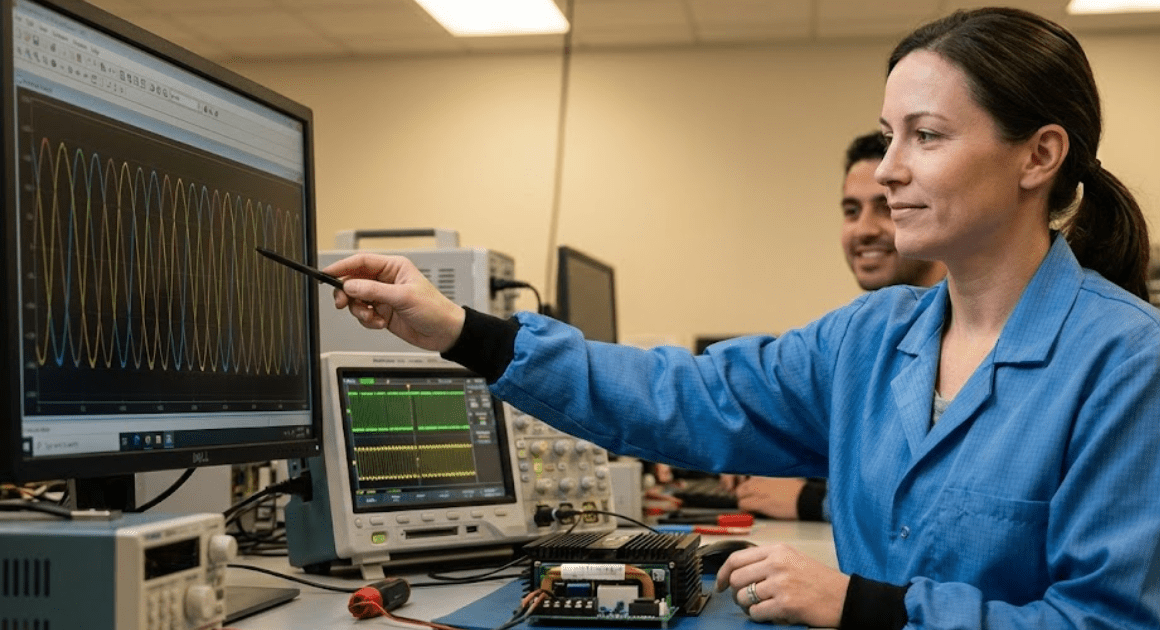
Crucially, theory by itself doesn’t instill the confidence to tackle real equipment. A student might ace an exam on converter topologies yet feel hesitant to design or experiment with one in the lab. This is because abstract knowledge hasn’t been translated into intuitive understanding or practical skill. Educational researchers note that computer simulations can bridge this gap by allowing students to put theories into practice in a realistic context. By interacting with EMT and converter models on screen, students begin to see how the equations play out in dynamic behaviour. For example, they can adjust the firing angle of a thyristor in a converter simulation and immediately observe the effect on voltages and currents – linking theory to tangible results. Without such experiences, theory remains an “on paper” concept, and students often lack confidence that they can predict or control what will happen in a real circuit.
Engineering educators have long emphasized the importance of moving from abstract to concrete learning. Simulation helps make the abstract become concrete, turning what might seem like dry, boring calculations into visual and interactive phenomena. In one study, introducing a simulation tool in a power electronics course “improve[d] the quality of teaching by making the abstract concrete [and] the boring interesting,” which in turn stimulated greater student interest. When students see a converter model come alive – with waveforms oscillating and responding to parameter tweaks – the subject matter clicks in a way that pure theory can’t achieve. This builds a much deeper understanding of EMT basics and converter operation, laying the groundwork for genuine confidence.
Safe virtual labs let students experiment without fear of failure
Even when students know what they are supposed to do, fear of failure can hold them back from trying it. In traditional high-voltage or power electronics labs, a simple wiring mistake can lead to blown components or safety hazards. It’s no surprise that fear of failure presents a notable barrier to learning and innovation, especially among engineering students. Students might hesitate to experiment or may follow lab recipes blindly, worried that a wrong move could damage expensive equipment or embarrass them in front of peers.
Virtual laboratories remove these worries by creating a risk-free space for exploration. Research on simulation-based learning finds that students often develop anxiety about performing experiments due to the perceived negative consequences of mistakes, but in a virtual lab “they can safely perform experiments… without any fear of damage to the equipment or injury to themselves.” In other words, simulations let students fail safely. No blown fuses, no public mistakes – just feedback and the chance to try again. This freedom to experiment, without the usual stakes, is transformative for learning.
Consider a few key benefits of safe, virtual lab environments for EMT and converter education:
- No risk, no fear: Students can flip switches, short nodes, or push a converter to its limits in simulation without real-world consequences. Freed from worry about equipment damage or personal harm, they focus on understanding functionality and cause-effect relationships. This encourages a mindset of exploration rather than avoidance.
- Learning from mistakes: Error is a great teacher – and in a simulator, mistakes become valuable lessons instead of setbacks. If a student configures a DC-DC converter incorrectly and sees an unstable oscillation result, that “failure” carries no penalty. Instead, the software provides immediate feedback and the student can adjust components or controller settings to correct the issue. This iterative trial-and-error builds problem-solving skills and resilience.
- Unlimited practice: Unlike physical labs constrained by time slots and hardware availability, virtual labs are always open. Students can repeat an experiment multiple times or tweak parameters at will. They might simulate an EMT scenario (like an inductive load switching surge) again and again, gradually intuiting how and why the transient behaves as it does. This unlimited, self-paced practice solidifies competence in a way one-off lab demos cannot.
By removing the real-world consequences, safe simulation spaces drastically reduce learning anxiety. Students no longer fear looking “inadequate” for a misstep, and they gain confidence with each hands-on attempt. In fact, educators have observed that this confidence carries over to real labs once students have honed their skills virtually. After all, if you’ve successfully navigated dozens of fault scenarios on a virtual microgrid model, you approach the physical equipment with much less trepidation. The result is a student who doesn’t just know the theory but feels ready to apply it.
Transparent simulation models turn abstract concepts into intuitive understanding
A major advantage of modern EMT and converter simulators is their transparency – students can literally see what’s happening inside a system. Unlike a physical circuit, where many processes are invisible, a simulation model exposes every voltage, current, and field variable for inspection. This transparency turns abstract concepts into something almost tangible.
For example, think of the concept of transient stability in a power system, or the switching behavior inside a PWM inverter. On paper, these are described by differential equations and abstract waveforms. In a transparent simulation, students can watch the system’s response unfold step-by-step: they might plot the rotor angle of a machine during a fault, or zoom in on the current spike when a transistor switches on. Complex equations transform into intuitive visuals. As one educational study noted, certain theoretical relationships “can be better understood by comparing simulation graphs” side by side. By overlaying the simulated current and voltage waveforms of a converter with the expected theoretical waveforms, students quickly grasp how the theory translates to reality – and where there are nuances that pure theory might gloss over.
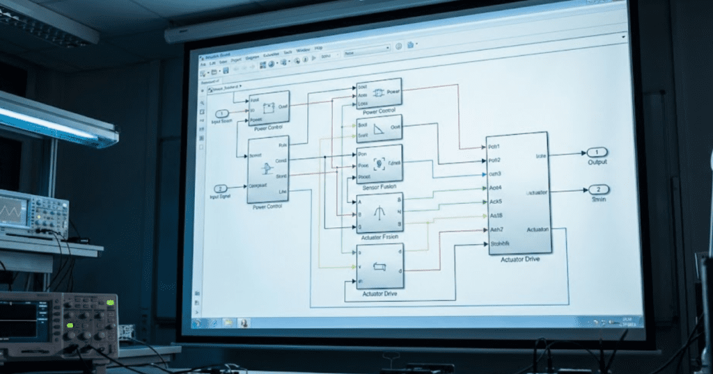
Another aspect of transparency is that simulation models are grounded in real physics, yet are user-friendly to interact with. Many widely used power engineering simulation packages (such as those built on MATLAB/Simulink) provide intuitive, graphical interfaces. Students build circuits by dragging and dropping components, much like drawing a schematic. They can double-click on any element to inspect or change its parameters. Since the underlying calculations are based on established EMT algorithms and converter equations, the outcomes remain faithful to what physics predicts – but the process of model-building and observation is accessible even to beginners. In effect, the simulator becomes a sandbox version of a power lab, where everything is visible and adjustable.
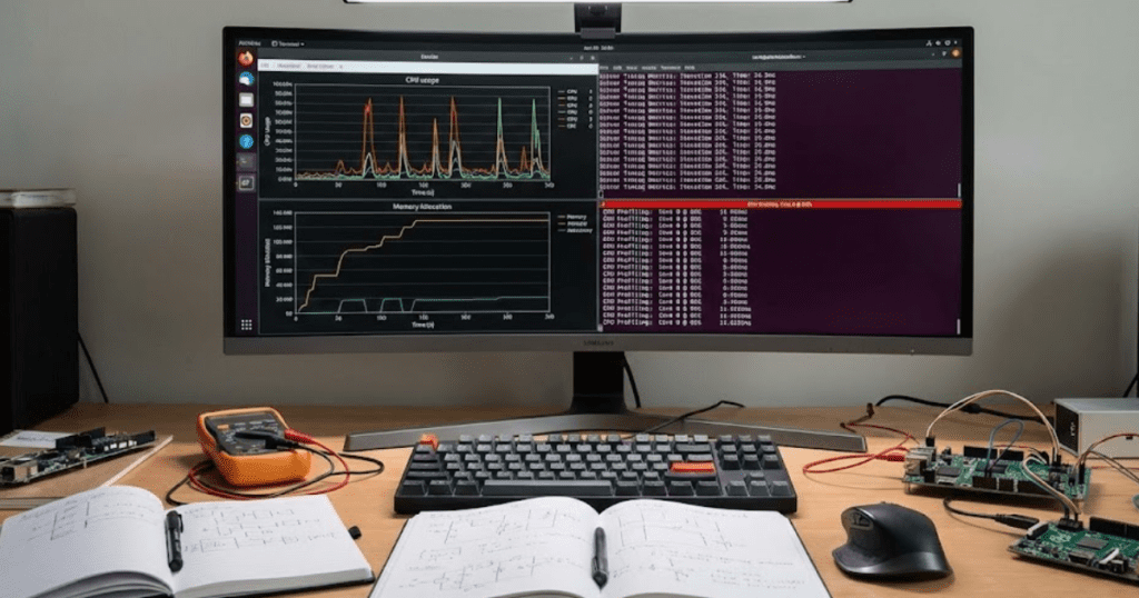
Transparency also means students can trace cause and effect through a system. If an EMT simulation shows oscillations after a circuit breaker operation, a student can pause and probe the model to find the root cause (perhaps a resonant LC path). If a DC-DC converter output is not as expected, they can inspect internal variables (inductor current, diode state, etc.) to diagnose why. This practice of opening the black box leads to deeper understanding. Instead of treating converters or transient phenomena as magical or inscrutable, students come to intuitively understand how each part of the system contributes to overall behaviour. One educator observed that using a visual simulation environment enabled instructors to demonstrate dynamic system behavior easily by changing inputs and showing students what happens in real-time, which “stimulates students’ interest” and engagement in learning power electronics. In short, transparent simulation models turn theoretical EMT and converter concepts into living, interactive lessons – building a strong intuitive foundation that pure theory teaching often lacks.
Guided exercises prepare students to tackle physical hardware confidently
“Guided exercises ensure that the first time a student encounters complex equipment, it is not truly the first time.”
While open-ended exploration is valuable, students benefit greatly from a structured path when first learning EMT and converter basics. Guided exercises – such as step-by-step simulation labs or progressive problem sets – provide scaffolding that helps beginners practise EMT fundamentals in a logical sequence. Starting with simple models and gradually increasing complexity prevents overwhelming novice learners, all while building their skill and confidence incrementally.
For instance, a guided exercise might begin with a basic RC circuit to illustrate a transient response, then add complexity: first a single-phase rectifier, then a full bridge converter with control, and eventually a grid-tied inverter system. At each stage, the exercise can prompt students to predict outcomes, run the simulation, and reflect on any differences. This approach ensures learners grasp core principles (like time constants or PWM effects) before piling on more layers. By the time they reach advanced scenarios, they have a toolkit of understanding developed through practice. Research supports this scaffolded approach – one study found that combining interactive simulations with guided problem-solving significantly improved students’ systematic problem-solving abilities in engineering courses (InSiDE simulations for dynamics education).
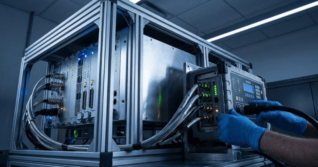
Moreover, guided simulation labs serve as a bridge to working with real hardware. They familiarize students with procedures and troubleshooting in a low-stakes setting. When the time comes to use physical equipment, students who have completed virtual exercises often perform far better. In one case, 94% of students reported gaining domain knowledge and confidence in their lab skills – and felt better prepared for in-person labs – after using virtual lab simulations as a practice tool. This is a striking validation that well-designed simulation activities can bolster real-world readiness. Students walk into the hardware lab having essentially done it before in the virtual world: they have seen the correct waveforms, made and corrected mistakes, and learned the workflow of an experiment.
Confidence grows hand-in-hand with competence. By practising EMT basics and converter operation through guided simulations, beginners steadily build both their understanding and their self-assurance. Instead of facing a high-power converter demo for the first time with uncertainty, they approach it like a familiar exercise. An illustrative example comes from a biology context where students first learned microscope operation in a virtual lab; instructors found those students were noticeably more adept and confident when handling the real microscopes later on. The same principle applies in power engineering: a student who has virtually debugged a faulty inverter model will feel far more confident troubleshooting a physical inverter in the lab. Guided exercises ensure that the first time a student encounters complex equipment, it’s not truly the first time – they have done it virtually, reflected on it, and are ready to succeed for real.
How SPS SOFTWARE supports student mastery
Building confidence with EMT and converter models begins with a learning space that feels approachable, structured, and safe, which is the same spirit carried into how OPAL-RT SPS SOFTWARE supports education. Students often advance more consistently when a modelling tool lets them start small and build knowledge layer by layer, and this is where clear, physics grounded behaviour matters. The platform offers an intuitive way to test ideas, review internal signals, and practise guided steps without fear of mistakes. This style of progression helps students connect theory to practical insight in ways that feel achievable at each stage. The result is a stronger sense of readiness when students eventually work with hardware in the lab.
Educators also benefit from having a modelling system that grows with the learner rather than limiting their curiosity. SPS SOFTWARE supports transparent component models, straightforward simulation workflows, and structured exercises that align naturally with the teaching of EMT basics and converter basics. Instructors can use these tools to reinforce lessons, demonstrate system behaviour visually, and create opportunities for independent exploration. As students gain confidence, they can move from simple circuits to advanced system studies using the same familiar environment. This cultivates a long term path for mastery while supporting the instructional goals of modern power engineering programs.